By Neal Michal, principal, Converting Expert LLC
There are several advantages of zero-speed splice unwinds in web-handling operations. Among these are a consistent, high-quality splice that rarely fails and a wide array of splice types. The real-world tension dynamics for a zero-speed splice will be presented in this article. A methodical approach to analyze each phase are described. Three different computer models will be introduced.
Editor’s Note: The first article in this series, “Benefits and challenges of designing and using accumulators in various web-handling operations,” appeared in the 2023 Q2 issue, pages 60-67.
Introduction
There are two broad categories of unwinds: R2R and continuous. R2R unwinds require the entire process to be stopped before splicing in a new roll. Continuous unwinds dramatically improve productivity because the process continues to run during a splice.
There are two types of continuous unwinds designated by their splicing process. A flying-splice unwind (aka “turret unwind”) makes a splice while the expiring roll is running at line speed. The other approach is to bring the expiring roll to a complete stop before making the splice. This is a zero-speed splice unwind. An accumulator is required to allow the downstream process to continue during the splice event (see author’s initial article referenced above).
This paper will focus on zero-speed splice unwinds. There are several advantages because the web is stopped. The primary benefit is a consistent, high-quality splice that rarely fails; the secondary is a wide array of splice types. Geometry options include both lap and butt splice. Tape or heat-seals are most common. Other splice types include ultrasonics, hot-melt adhesive and sewing. Additional benefits include a short splice tail that will not wrap up downstream. Some splices can be sold into the final product, which will further reduce waste. Benefits come with challenges. The tension dynamics associated with an accumulator are the leading cause for wrinkles, neckdown and web weave.
General arrangement for zero-speed splicers
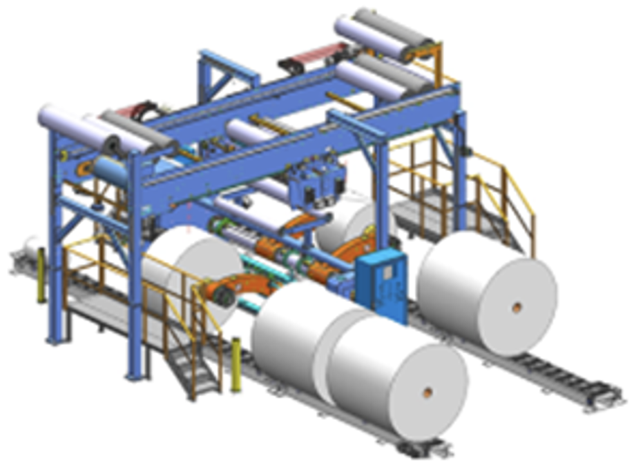
Zero-speed splicers come in all shapes and sizes. Unwind speeds typically depend on the capacity of the accumulator. The unwind shown in Figure 1 can splice heavy rolls of paper at speeds of up to 1,000 mpm (3,280 fpm). It features a horizontal accumulator located above the unwind. The carriages are servo-actuated with a separate dancer to set tension.
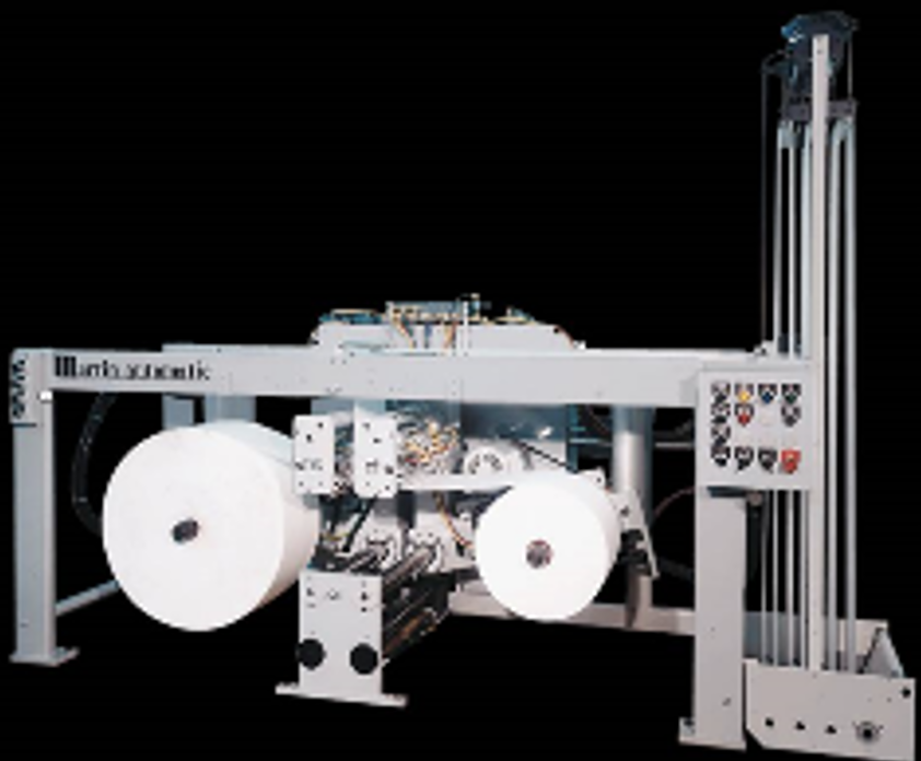
The unwind shown in Figure 2 is common for narrow-web applications such as label printing or a diaper-converting machine. It features a vertical accumulator with a single moving carriage. Both types of unwinds operate in a similar fashion. This paper assumes the second style.
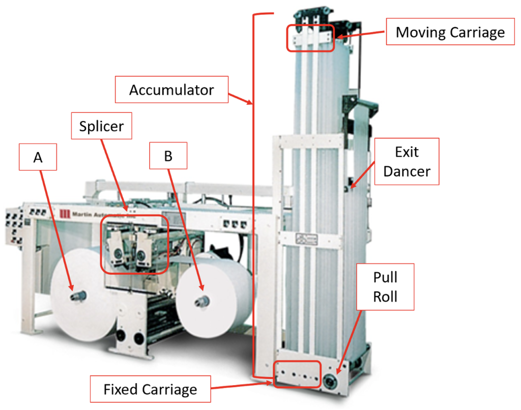
The following info is specific to the unwind shown in Figure 3. Both spindles are driven to improve dynamic performance. This splicer is designed for a tape lap splice via hot-wire cutoffs. This accumulator features three rollers in the moving carriage. They are shown at maximum height (aka “100% fill”). The accumulator cylinder is connected to the carriage via cables and pulleys, and air pressure is used to generate tension in the accumulator. Total accumulation capacity is six times the maximum carriage movement. A driven pull roll is preferred to reduce wrinkles, and a linear dancer is used to set downstream tension.
Overview of the splice sequence
For most unwinds, the “run height” of the moving carriage is set low to avoid wrinkles. When a splice is commanded, the carriage will rise slowly to “splice height.” “Delta Fill” is the difference between splice and run heights; this metric determines the total length allowed for a splice event.
Once at splice height, the position loop for the accumulator will be turned off. The expiring spindle will be commanded to decelerate to a full stop. Splice bars then will be closed to attach the webs. The expiring web is cut below the splice bars, which then open, and the new roll is commanded to accelerate back to full speed. Shortly after this, the position loop will be re-enabled for steady-state operation.
It is common to use 50-60% of the Delta Fill to stop the expiring roll and make the splice. Likewise, another 30-40% of the Delta fill is required to accelerate the new roll back to line speed. The last roughly 10% is used to smoothly transition the unwind back into position-loop control, with the objective being a “soft landing” back into steady-state operation.
Recall that the downstream process never slows down. During the splice event, the individual span tensions will vary considerably; luckily, this happens in a repeatable fashion. (Nominal tensioning for an accumulator was described in the author’s first article; tension dynamics and optimization will be discussed in the third article.)
Best practices
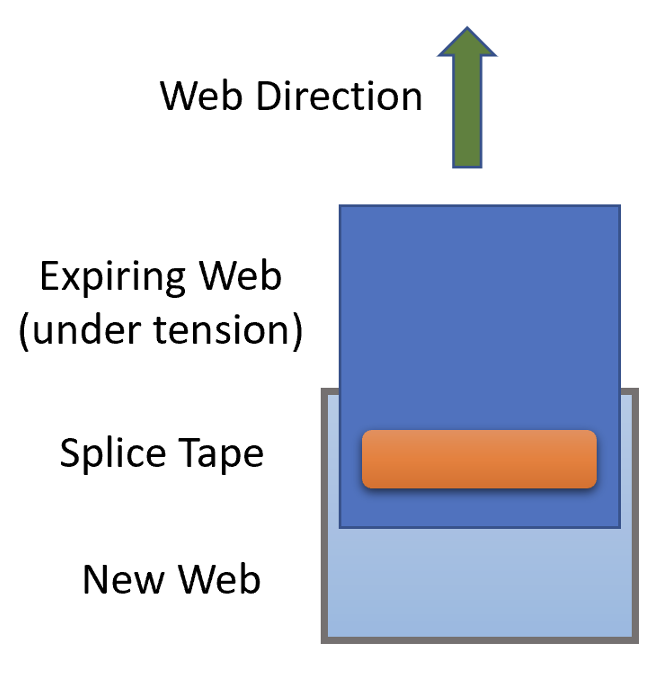
Document Splice Setup: A successful splice begins with a proper setup. Work with your OEM and senior operators to determine a best practice that will be used consistently. If using tape, the width and position of the tape is important (see Figure 4). In general, heat-seal splices are easier to set up and provide better web handling as the new roll ramps up. Take pictures, write up standard operating procedures, make a video. Use this information to train the other operators as necessary. The standard is to never miss a splice. Expect nothing less.
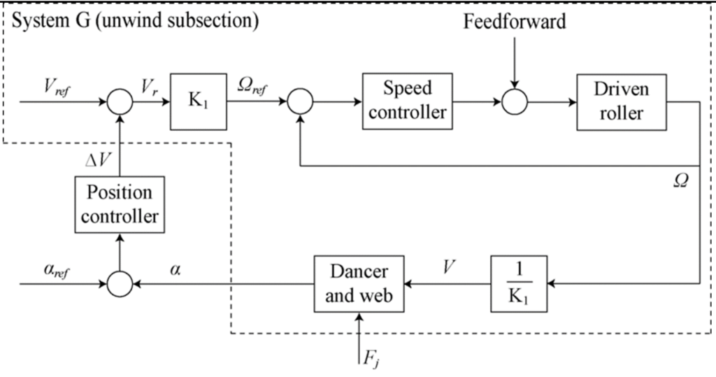
Position Loop: A position loop is used to control the height of the accumulator (see Figure 5). The spindles are controlled using an inner velocity loop for nominal RPMs based on roll diameter and pull-roll velocity, with an outer position loop trimmed by carriage height. During slow-speed fill, the target setpoint for height is adjusted in the controls using an S curve. The position loop is turned off during the deceleration and acceleration phases, and then it is re-established once the new roll has been brought up to speed.
Roll Diameter: Recall that the inner control loop is velocity. Web velocity is spindle RPMs x roll diameter x Pi. It is important to know the new roll diameter to avoid poor velocity control. A ratio detector can calculate roll diameter very accurately with knowledge of spindle RPM and pull-roll velocity. However, a ratio detector can take up to three seconds to establish diameter for a new roll, and many ugly things can happen in three seconds. A diameter sensor is the best approach to ensure the new roll is accelerated to the correct speed. Accurate roll diameter is essential for inertia-compensated controls (see below).
Delta Fill: Delta Fill is the difference between splice and run height. Carriage position typically is measured in % of full capacity. For a splice height of 75% and a run height of 25%, the Delta Fill is 50%. The Delta Fill is an important metric as it relates to process speed, splice time, deceleration rate to stop the roll, and acceleration rate to bring the new roll up to speed. Several designs of experiment (DOEs) may be required to find the best combination for these variables.
Calculate Tension: Web tension is the most important parameter for any converting process. If the unwind does not have calibrated load cells, calculate the nominal tension based on cylinder geometry and the number of spans. This will provide the average span tension. Divide by web width to obtain intrinsic tension values of N/m or pli. (175 N/m = 1 pli).
Establish Tension Setpoints: Equipped with tension calculations, it now is time to determine the ideal tension. Use a DOE to determine the ideal tensions. Intrinsic units will allow the air pressure to be adjusted for different web materials (EG widths, caliper, modulus).
Slow-Speed Fill: Slow-Speed Fill is the rate that the carriage is moved to splice height. During this time, the tension differential across the accumulator will increase. The magnitude of the tension differential will vary linear to the carriage velocity. There is no need to rush the movement to splice height.
Decel Rate: The decel rate is used to stop the expiring roll. How fast should you stop the expiring roll? Typically, the units for decel rate will be meters per minute (mpm) or feet per minute (fpm). When bringing the roll to a stop, the tension at the entrance of the accumulator will momentarily shoot up; the span tension at the exit of the accumulator will conversely drop. Determining the correct decel rate requires significant attention to detail. Failure modes include excessive neckdown, troughing in an open span, wrinkles across rollers and hard folded creases.
In general, use the fastest decel rate possible that avoids neckdown or wrinkles. If a large roll has to be spliced out, it is a good idea to slow the overall process down to improve splice reliability.
Splice Time: Splice Time includes the total time that both spindles are stopped. A tape splice may only require 0.50 second. A heat-seal splice will require more time. The time to cool off a heat-seal often is 2-3x longer than the required time to fuse the webs together.
Accel Rate: The weight (inertia) of the new roll is an important factor on what acceleration rates can be used. Typically, they will be ~60% of the deceleration rate. When bringing the new roll up to speed, the tension at the accumulator entrance will drop; the exit tension will increase. Failure modes include running off of the core (too slow), expansion wrinkles at the entrance with delicate webs (too fast), loss of web tension (too fast) or telescoping the new roll (way too fast).
Inertia Compensation: (Excerpts from my colleague Clarence Klassen, P. Eng.) Drive-speed regulators are incredibly accurate at a steady speed. The inertia of both rolls should be considered to improve the dynamic performance of any high-speed splicing operation. Roll inertia increases as the 4th power of diameter. Refer to the previous roll-diameter discussion. A feed-forward technique is recommended to compensate for the rotational moment of inertia of the unwinding roll. Inertia compensation also depends on the inertia of the motor, roller and shafts – particularly for smaller rolls. New inertia calculations may be required if you run rolls with significant differences in roll density.
Once inertia compensation is established, it should be tested by accelerating a roll that has been taped up (tail to the roll OD). The speed-regulator output will not change if the inertia compensation is correct.
Analyze Splice Failures: Recall that zero failures are the expectation. If any splice is missed, the root cause must be established. Find the end of the roll somewhere downstream of the unwind. The evidence should be there. Did the tape fail? Did the heat-seal itself pull apart? Was the new web partially severed by the cut-off wire located on the other side of the splice bar?
Install Load Cells: Recall that during decel and accel, span tensions will vary. Adding load cells is a proven method to document and understand how tensions vary. If only one load cell is pursued, it should be located at the accumulator entrance because this is where the greatest tension variations take place. A second load cell at the accumulator exit will provide additional insight. A third load cell may be used to monitor or set tension for the downstream process.
Web-Width Sensors: The installation of web-width sensors can be helpful for delicate webs. Excessive wrinkles or edge foldovers can be detected because the web width will change. If the sensors are located at the accumulator entrance, the data can be used to find the ideal deceleration rate. If the sensors are located at the accumulator exit, they can determine if the web steers laterally as a function of carriage height.
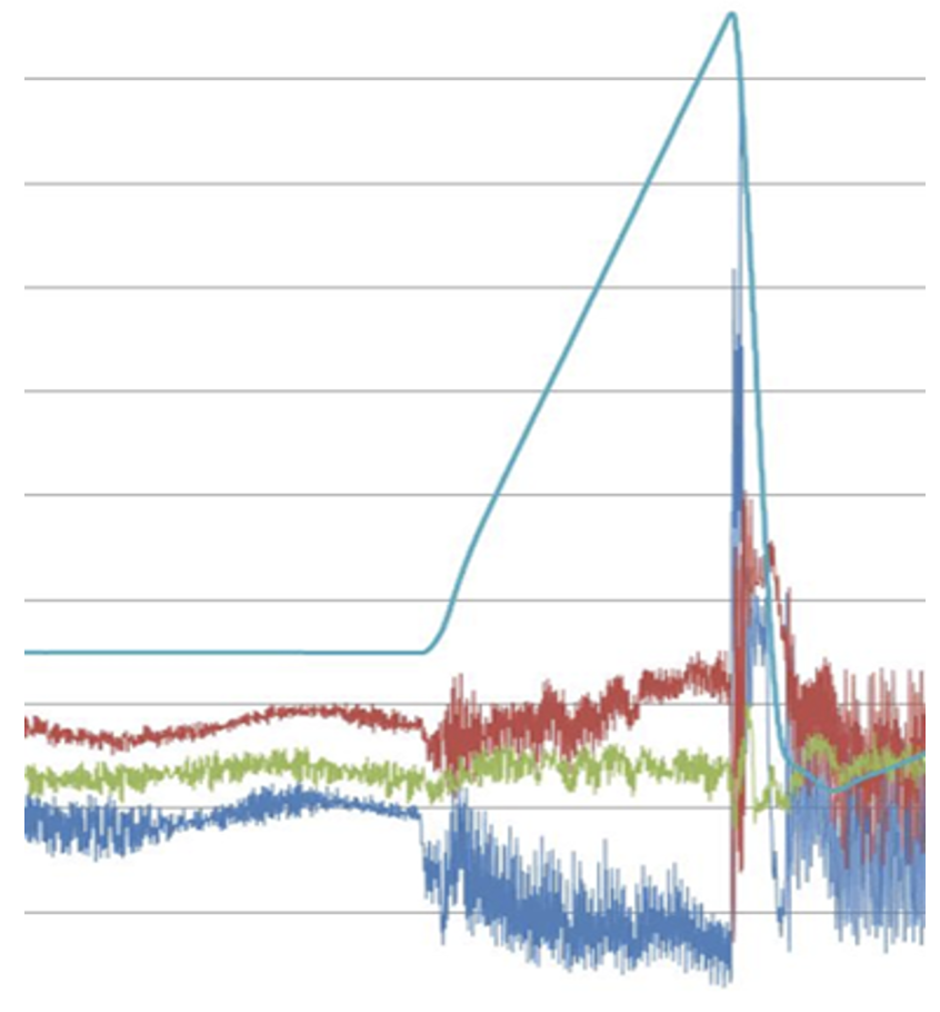
Trend Charts: Trend Charts are required to optimize a zero-speed splice event. Parameters should include roll diameter, spindle velocity & torque, carriage height, tension setpoint and actual tensions and width, if available. Resolution should be set high if actual tensions will be analyzed. Trend charts should be held for at least four days. This will allow one to analyze a failure over the weekend. Figure 6 shows how tension varies during the splice event on a high-speed process. This graph will be discussed at length in my next article.
Video Recorders: Perhaps 90% of all splice failures can be caught and analyzed with a smartphone or digital camcorder. However, one must be standing in the right place during the splice event with the video running. You will miss it; trust me. Permanent cameras and a digital video recorder (DVR) are key to capture and analyze splice failures after they occur. Who likes getting called in on the weekend?
Conclusions
Continuous unwinds can dramatically improve productivity because the downstream process continues to run during a splice. A flying-splice unwind makes a splice while the expiring roll is running at line speed. A zero-speed splice unwind requires an accumulator to feed the downstream process while the web is stopped to make a splice.
There are several advantages. The primary advantage is a consistent, high-quality splice that rarely fails. Splice geometry includes both lap and butt-joint types. A range of sealing options are available: tape, heat-seal, ultrasonics, hot-melt adhesive and sewing. The short to non-existent seal will not wrap up downstream. Some splices can be sold into the final product without the need to cull them from the roll(s). More than a dozen best practices have been described.
Benefits come with challenges. The tension dynamics in the accumulator is the leading cause for wrinkles, neckdown and weave during the splice event, and this is particularly important for delicate webs. Tension disturbances follow a repeating pattern.
Editor’s Note: Tension-disturbance patterns and how to optimize the splice sequence will be discussed in the third installment of this series in the 2023 Q4 issue. A proven method to quickly establish good run setting will be offered.
References
- “Benefits and challenges of designing and using accumulators in various web-handling operations,” Neal Michal; Converting Quarterly; 2023 Q2.
- “Nonwovens Converting Performance,” Neal Michal, 2022 AIMCAL R2R USA Conference, September 2022.
- “Modeling and Computer Simulation of Zero-Speed Splice Unwinds,” Prabhakar Pagilla, International Web Handling Conference (IWEB 15), Web Handling Research Center, June 2019.
- “Impact of Web Permeability on High-Speed Web Transport,” Paul Beuther, Neal Michal, International Web Handling Conference, Web Handling Research Center, June 2015.
- “Fixed-Order H-Infinity Tension Control in the Unwinding Section of a Web Handling System Using a Pendulum Dancer,” Gassmann, Knittel, Pagilla, Bueno; IEEE Transactions on Control Systems Technology, 2012/01/01.
- “Analysis of Web Wrinkling in an Accumulator,” Neal Michal, Balaji Kovil-Kandadai, Amol Patel; International Web Handling Conference (IWEB 11), Web Handling Research Center, June 2011.
- “Web Tension in an Accumulator and Industry Needs for the Future,” Neal Michal, International Web Handling Conference (IWEB 10), Web Handling Research Center, June 2009.
- “Practical Considerations for Zero-Speed Splice Unwinds,” Neal Michal, AIMCAL AWEB 2008.

Neal Michal, principal at Converting Expert LLC, has a 36-year career focused on making and converting web products. He was Kimberly-Clark’s senior web-handling expert and led open innovation efforts at the Web Handling Research Center for two decades. Neal was responsible for winding and converting performance. During this time, he led computer modeling efforts for winding, wrinkling, accumulators and tension control. Neal launched Converting Expert to help companies improve capability, productivity and delivered quality. Neal is a technical advisor to the Assn. for Roll-to-Roll Converters (ARC) and launched its Web Handling Committee. He presents training at R2R conferences and is a contributor to Converting Quarterly. Neal can be reached at 770-356-7996, email: neal@convertingexpert.com, www.convertingexpert.com.

