By E. J. (Ted) Lightfoot, Ph.D., principal, Ted Lightfoot LLC
Introduction
Slot-die coating currently is the most widely discussed coating method. This is partially due to the large body of scientific knowledge on slot-die and partly due to its use in manufacturing advanced-materials applications, such as batteries and fuel cells, as well as academic investigations of perovskite solar cells. But the popularity also is driven by the utility of slot dies operating in “premetered” mode.
There is a plethora of conflicting advice available on how to do slot-die coating, including what die configuration, line speed and viscosity range to use. It turns out that the most common die configurations can operate in at least five different fluid-mechanical regimes, and the diversity in advice largely results from assumptions about what regime people choose to operate in.
There are seven common configurations of slot-die coating (tensioned web, contact die, proximity die with or without a vacuum box, short-drop curtain coating, extrusion coating and die curtain coating). The most common of these are proximity die coating with and without a vacuum box. The vast majority of what is known and said about “slot die” coating refers to proximity die coating. Proximity die coating is characterized by a rigid backup roll supporting the coated web while the die is positioned “in the proximity” of the web surface with a defined gap of a few mils between the die face and the web. A thin “bead” of liquid bridges the gap between the die face and the web. The fluid mechanics in this bead determine the unique characteristics of proximity die coating.
The liquid bead between the die face and the web may be stabilized for high-speed coating and thin coatings by a vacuum box on the upstream side of the die. However, the use of a vacuum box is a matter of some debate: Those seeking thin coating and high coating speeds generally use vacuum boxes. Those coating at low speed and requiring optical quality often eschew the vacuum box, dismissing it is a crutch that introduces new classes of defects. This difference of opinion is an obvious result of people operating in different fluid-mechanical regimes (in this case, different ranges of line speed and thicknesses).
What are “fluid-mechanical regimes”?
A basic definition is different ranges of conditions that lead to qualitatively different fluid behavior. The most familiar example is the transition from laminar to turbulent flow in pipes that occurs at a Reynolds number (Re = dVr/m where d is the tube diameter, V the average velocity, r the density and m the dynamic viscosity) around 2100. Turbulence in coating flows is rare. The common regimes of slot-die coating are differentiated by features of the operating window as the line speed varies.
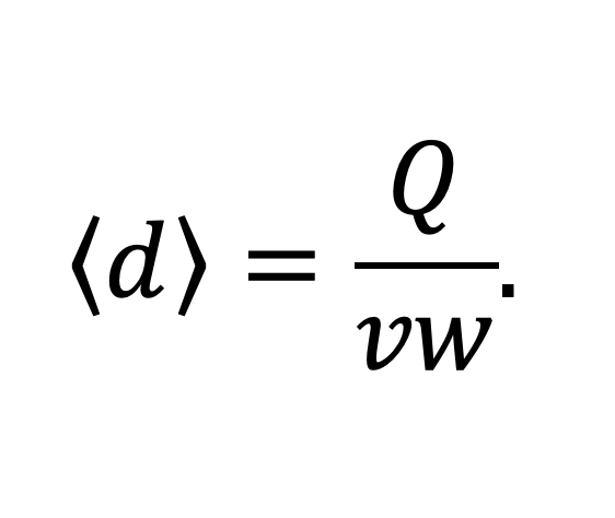
There are several ways to visualize the operating window for a slot-die coater. Because the flow to the die is controlled by a metering pump delivering a volumetric flow Q, to a web moving a line speed, v, over a coated width, w, the average wet-coating thickness, <d> is shown in Equation 1.

This feature is called premetered coating [1]. In general, premetered coating is better understood than self-metered coating. There are many theories [2] for the behavior of the coating window for slot-die coating, ranging from simple asymptotic results to mathematical models that predict the effects of die geometry.

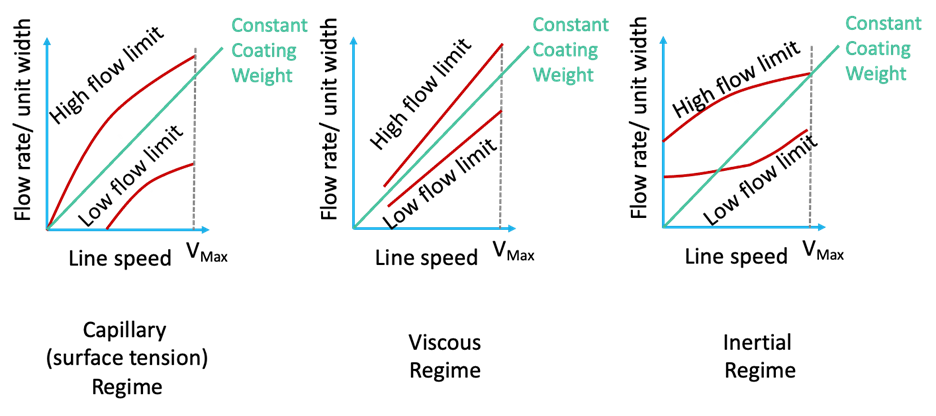
It often is helpful to look at the operating limits of flow rate vs. line speed as sketched in Figure 1. The exact shape of the window is a function of die geometry as well as any non-Newtonian effects.
We can set any average wet thickness we want by controlling the flow rate to the die; however, there is a minimum thickness at which the smooth coating breaks down into gross defects. This minimum thickness is called the low flow limit. There also is a maximum thickness that can be pulled through the die without running back on the web. This is known as the high flow limit. In general, because we can lower the flow by dropping pump speed, the low flow limit is more significant than the high flow limit.
Patterns of defects at low flows
The pattern of defects we see as we drop below the low flow limit depends on coating speed and how far below the limit you are attempting to coat. Kasischke, et al, studied the effect of Reynolds number (based on the downstream gap for a length standard) [3].
At Reynolds numbers on the order of 0.1 (which had Capillary numbers on the order of 0.02), the first pattern encountered is likely to be alternating stripes of coated and uncoated material running in the machine direction (known as rivulets or break lines); at lower Reynolds number and higher Capillary numbers (on the order of 0.1), the first pattern encountered is likely to be bars (not necessarily straight) of coated material running in the transverse direction; at intermediate Reynolds numbers (0.02 to 0.05) and Capillary numbers, there may be a mixed pattern of machine-direction and transverse-direction defects.
As the flow rate gets progressively lower, various other chaotic patterns may occur and at low enough flow, the coating breaks down into discrete dots. The application of a vacuum to the bead introduces other defects and other complications. At commercial speeds, break lines often are the first defect seen.
A closer look at the key regimes
Meniscus regime: At very low speed and viscosity (Capillary numbers approaching zero), the pressure drop in the distribution chamber can become too low to control the coatweight profile using a conventional die design, and the coater becomes a die-fed meniscus coater. There is no hard number that characterizes this regime, although pressure drops through the die below roughly 10 psi are suspect. Coating in this regime with a general-purpose slot die is not recommended, although it is not uncommon to find people doing so through an unfortunate sequence of developments.
However, there are specialized meniscus-coating dies designed to run in this regime, as well as a number of other coating methods that might be considered. These include, alphabetically, air-knife, dip, gravure, knife, Mayer rod, meniscus [either stationary roll (a.k.a. kiss)] and Microgravure™. All are obvious alternatives; various other roll coaters may be worth considering as well.
Capillary regime: Operating at low Capillary number (but with high enough viscosity or shear rate to allow the die to control flow distribution) is referred to as operating in the capillary regime (or the “surface tension regime”). In this regime, the minimum coatable thickness decreases as the Capillary number (i.e., the line speed) increases or the gap can increase as the line speed decreases. Were it not for the flow patterns that arise from the low flow limit, running a slot die with a higher gap would improve coating uniformity (the effects of gauge variations in the substrate and mechanical imperfections in the die and coating roll would be minimized). The low flow limit then can be thought of as providing a maximum gap you can use at a given wet thickness and usually is expressed as the gap over the minimum thickness. Minimizing the constraints of the low flow limit is another reason people making optical-quality coatings tend to run at low speed and low viscosity.

Viscous regime: As viscous forces become more important, the Capillary regime gives way to the Viscous regime (sometimes called the visco-capillary regime). In the viscous regime, the low flow limit becomes insensitive to Capillary number. This is the regime most commonly recommended for general-purpose slot-die coating: It is a higher-speed regime than the capillary regime and allows for more concentrated (higher viscosity) coatings that dry faster as well. Typical recommendations for viscous-mode slot-die coating call for viscosities on the order of 100 cP and line speeds of 50 fpm or more (the Capillary number for 100 cP, 50 fpm and a surface tension of 25 dynes/cm is one). For Newtonian liquids, the maximum gap in the viscous regime is roughly 1.7 times the wet thickness [4]. At Capillary numbers characteristic of the viscous regime, care must be taken to manage dynamic wetting [5].
Inertial regime: The inertial regime is distinguished by a high Reynolds number (defined with the gap as the length scale), a high Capillary number, and a high ratio of Reynolds number to Capillary number (i.e., a high Physical Property number Pp= Re/Ca=rs*Gap/m2) [6]. In the viscous mode, the downstream meniscus of the coating bead is highly curved. In the inertial regime, the presence of an inertial boundary layer pushes the downstream meniscus back toward the exit: the faster you coat, the less restrictive the low flow limit is. In industry, the highly curved meniscus of the capillary and viscous regimes is sometimes referred to as “drawing mode” while the inertial regime, with its gentler downstream meniscus is called “wiping mode.” There are dies with extended lips sold to promote coating in the inertial (wiping) mode. However, to get to this extended operating window, the line speed needs to be above a minimum value (as shown in Figure 1).
Blade-coating regime: There is one more regime for slot-die coating that differs from the other four in that it is not strictly a premetered coater. This regime, called the “blade-coating regime,” is not well documented in the literature; however, it appears to be common – at least in the battery industry [7]. In the blade-coating regime, the die is tilted toward the coating, and the downstream die lip is used for physical thickness control: scraping off excess coating – much like a lip coater. In a sense, this operates above the high flow limit because excess coating drips off the downstream side of the bead. This configuration is reported to be sensitive to ribbing at high speed and leads to high die wear; nonetheless, it smooths the high edges (with an accompanying change in coated width).
Summary
The purpose of this paper was to put advice about slot-die coating into perspective. Much of the contradictory advice on operating ranges for viscosity and line speed result from confusion over which operating regime the “experts” assume you have chosen. But the choice of operating regime is more nuanced than many realize.
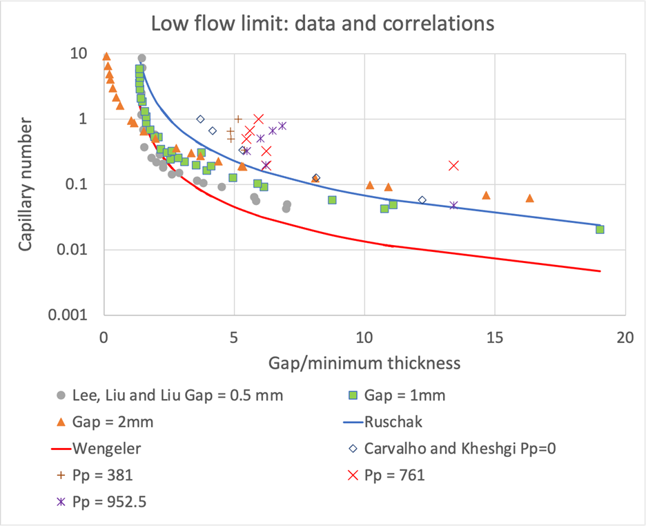
Figure 2 shows that the effect of increasing Reynolds number on the low flow limit is visible at Capillary numbers far below one (where the Reynolds number may be on the order of tens, not hundreds). It also is important to remember that many coatings exhibit shear-dependent viscosity: You want to use the viscosity one might expect in the nip [8]. This is a case where doing basic dimensional analysis clarifies your options far more effectively than listening to the advice of experts.
References
- Ruschak, K.J., “Coating Flows,” Annual Reviews of Fluid Mechanics (1985) 17 65-89, http://doi.org/10.1146/annurev.fl.17.010185.000433
- Ding, X., Liu, J. and Harris, T.A.L. (2016), A review of the operating limits in slot-die coating processes. AIChE J., 62:2508-2524. http://doi.org/10.1002/aic.15268
- Kasischke, M., Hartmann, S., Niermann, K., Smarra, M., Kostyrin, D., Thiele, U., Gurevich, U.L., (2023), Pattern formation in slot-die coating. Physics of Fluids 1 July 2023; 35 (7), 074117. http://doi.org/10.1063/5.01500340
- See Sections 17.4 and 17.5 of Schweizer, P.M. (2022) Premetered Coating Methods: Attractiveness and Limitations, Springer Cham. http://doi.org/10.1007/978-3-31-014180-8
- Blake, T.D., ISCST Insights: An introduction to wetting and its relevance to coating (2017), Converting Quarterly 2017 Quarter 1, 7(1) 88.
- Carvalho, M.S. and Kheshgi, H.S. (2000), Low-flow limit in slot coating: Theory and experiments. AIChE J., 46: 1907-1917. http://doi.org/10.1002/aic.690461003
- Telep, David, “Lithium-Ion Battery Cell R2R Manufacturing” (2017) AIMCAL Fall R2R Conference.
- Romero, O.J., Scriven L.E., Carvalho, M.S. (2006) Slot coating of mildly viscoelastic liquids, Journal of Non-Newtonian Fluid Mechanics, 138(2-3) 63-75 http://doi.org/10.1016/j.jnnfm.2005.11.010
- Lee, K.Y., Liu, L.D., and Ta-Jo, L. (1992). Minimum wet thickness in extrusion slot coating. Chemical Engineering Science, 47(7), 1703-1713. http://doi.org/10.1016/0009-2509(92)85018-7
- Ruschak, K.J. (1976). Limiting flow in a pre-metered coating device. Chemical Engineering Science, 31(11), 1057-1060. http://doi.org/10.1016/0009-2509(76)87026-1
- Wengeler, L., Peters, K., Schmitt, M., et al. Fluid-dynamic properties and wetting behavior of coating inks for roll-to-roll production of polymer-based solar cells. J Coat Technol Res 11.65-73 (2014). http://doi.org/10.1007/s11998-013-9483-5
E.J. (Ted) Lightfoot, principal at Ted Lightfoot LLC, holds a B.S.E. from Princeton and an M.S. and Ph.D. from the University of Illinois at Urbana Champaign (all in Chemical Engineering). He worked for DuPont for over 35 years in film casting, coating and laminating. Ted’s experience includes R&D, plant support, being a Six Sigma Black Belt for Growth, and helping customers develop and troubleshoot processes and products. He currently is a consultant, writer, speaker and teaches short courses. Ted can be reached at 716-449-4455, email: ejl@TedLightfoot.com, www.TedLightfoot.com.

