By Orang Vahid, Ph.D., dir.-Application Engineering, Maplesoft; and Steve Lange, managing member, ProcessDev LLC
Due to increased demand for consistent quality and faster turnaround times when ordering new web-handling systems, machine designers are turning to simulation to stay ahead of the competition. Simulation models that include dynamical aspects have the advantage over manual calculations in that they can reflect the physical system as it changes during operation. As the process engineer seeks to reduce harmful web behaviors (e.g., slippage and wrinkling) caused by tension-control issues or roller misalignment, having a virtual method to determine when and where they may occur makes the system more robust. In this article, we present a modeling approach for roll-to-roll (R2R) systems that gives a convenient alternative to working with physical prototypes or running validation tests in a production environment. We introduce R2R-system modeling and simulation and show how it is used in identifying slippage, wrinkling and roller alignment problems.
System-level modeling and simulation
The terms modeling and simulation can take on many different meanings and are used to convey vastly different methodologies. Here, we will discuss the simulation of dynamical systems – systems that consider excitations in the form of force or torque and produce responses in the form of motion or, more generally, quantities that change over time. In the context of web handling, this approach combines drives, controllers and mechanical properties of the rollers and web materials to predict system behavior, such as the tension and strain variations in the web.
System-level simulation of a physical system requires the following pieces:
- A modeling environment where the user easily can capture relevant aspects of the system using pre-existing model building blocks (e.g., geometry, material properties, inputs [actuations] and outputs [sensors])
- A method to convert or translate the model layout to a set of equations that can be solved numerically
- One or more solvers to solve the resulting differential-algebraic equations
- An environment to display and review the results
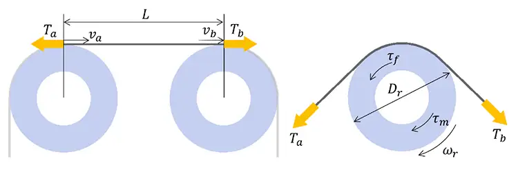
A block-diagram approach is used here to capture the system specifications and to create a model. Just as an introduction, we will look at the equations behind two of the most basic blocks in their simplest form: the span component and the roller component (see Figure 1).
Each span component (i.e., the web between two roller components) represents the conservation of mass equation in the form given by Equation 1, where L is the length of the span, ϵa,bare the web strains and va,b are the web velocities. Subscripts a and b represent the upstream and downstream ends of the span [1].

Each roller component in its simplest form (i.e., no slippage, misalignment or eccentricity) captures the relationship between web tensions on each side, roller inertia and bearing drag [2]. This is shown in Equation 2, where Dr is the effective roller diameter, τm is the motor torque (zero for an idler roller), Jr is the roller inertia, fb is the coefficient of bearing drag, ωr is the roller angular velocity and is the roller angular acceleration. Ta and Tb represent the upstream and downstream web tensions, respectively.

Dynamics and control: Unwind with dancer
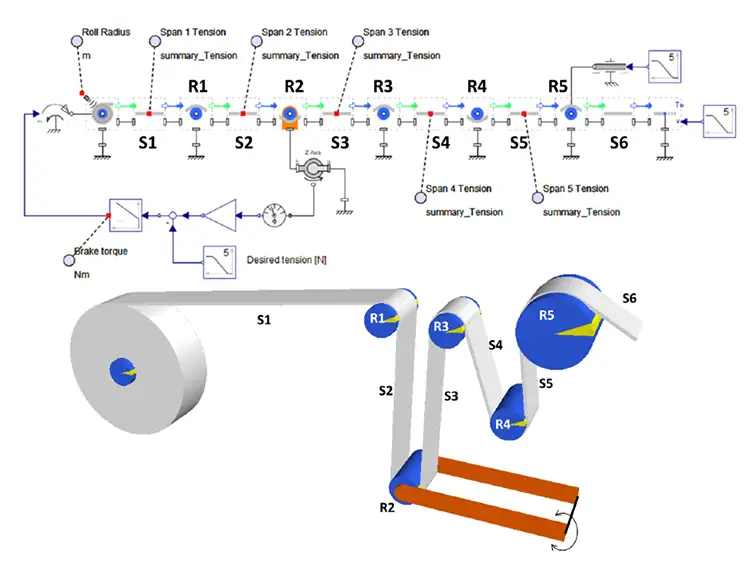
Figure 2 shows a system-level model representing the unwind portion of a web line with a dancer to control the tension. One immediately can identify some of the components used in this model, such as the unwind roll, various idler or driven rollers and the spans.
Here, we have a dynamical system for the tuning of the PID-control feedback to the unwind brake. Some of the features of this model include:
- The dynamics of the dancer, including preloaded spring, weight of the roller and arms, pivot friction and encoder
- Adjustable unwind scenarios created by defining the desired tension, web speed and downstream tension profile
- Adjustable web-material properties
- Adjustable PID gains for the unwind brake
- Adjustable roller bearing drag
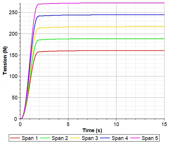
Figure 3 shows a sample of the simulation results that includes the simulated tension in Spans 1 to 5.
Web slippage
In most applications, the loss of traction is something to be avoided. The resulting web slippage on a roller can affect product quality. Under dynamic conditions, the ability to predict the onset of traction loss is important in the design process. Simulation can be used to discover such cases and to devise a robust solution by testing various design changes quickly: increasing line tension, changing the wrap angle, surface conditions (coefficient of friction) or even using a vacuum roller.
The maximum tension difference on either side of a roller is given by the Capstan formula [3], where μ is the coefficient of friction (COF) between the web and roller surface, β is the wrap angle in radians, Ta is the low tension, and Tb is the high tension.
Once a simulation is completed, one can compare the web tensions on either side of each roller against the Capstan limit, Equation 3, to check for the possibility of slippage.

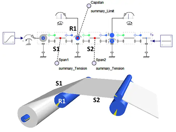
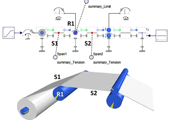
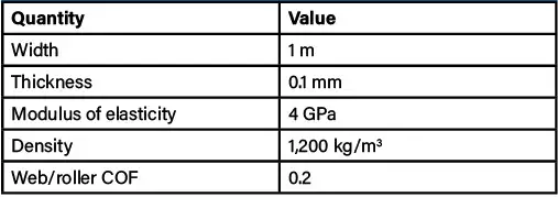
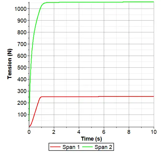
Consider the system shown in Figure 4. Here, the downstream web speed is set to 5.01 m/s. Both the roller (R1) and the nip are under speed control and have surface velocities of 4.99 m/s and 5 m/s, respectively. The web material properties are given in Table 1. The unwind break torque is increased to 50 N.m in 1 sec. The simulated web-tension time histories before and after the roller (R1) are given in Figure 5.
The model also calculates the wrap angle for any given roller in any given configuration. Here, for the Roller R1, the wrap angle is increasing slowly due to the shrinking unwind-roll diameter. The wrap angle starts at 22.6° and increases to 22.9° over the selected simulation time. The COF is set to 0.2, we can clearly see that the tension difference is much larger than the Capstan limit (Tmax) (@t=10s): Ta =255.8 N, Tb=1057.8 N >> Tmax=255.8 • e0.2•22.9•π/180= 277.1 N.
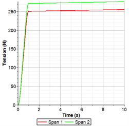
Because the Capstan limit is violated, the simulation results are not correct. To predict what actually happens to the web tension as the result of slippage, we add the slippage formulation to Roller R1 and re-simulate. Figure 6 shows the results of this new simulation.
There are many changes one can make to this model to try and eliminate the slippage. Some of these changes include:
- Reducing the speed difference between the driven roller and the nip roller
- Increasing the friction on the driven roller
- Repositioning the Roller R1 or the unwind drum to increase the wrap angle.
Web troughs and wrinkles
A very common issue for web handlers is avoiding or eliminating wrinkles, fold-overs and creases in webs. Webs are very thin relative to their other dimensions and, in some mathematical models, have been considered as shells or plates that can buckle under compressive stresses. Troughs, or waves, can be observed in open spans in moving webs, and if these are significantly large, they can make their way over a roller into a downstream span, and they are termed “wrinkles.”
Compressive stresses can come from many sources, and we will discuss two of them: over-tensioning and misaligned rollers. Here, we consider the web-line shown in Figure 7. The blue rollers are driven, whereas the grey rollers are idlers but have bearing drag.
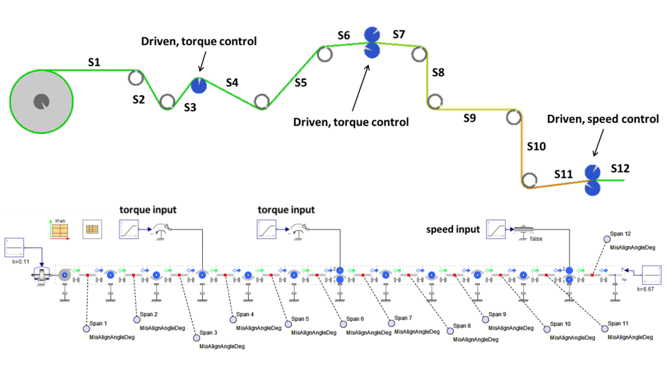
We also consider the same line running two different web materials as listed in Table 2.

Over-Tensioning: Tension in the web induces compressive stress due to the Poisson contraction. This, in turn, can lead to buckling and the formation of troughs at high-tension values. Tall troughs, which are narrowly spaced, can collapse to cause wrinkles and fold-overs. Following [4], the trough amplitude and its wavelength in a tensioned web are given by the Equations 4 and 5.
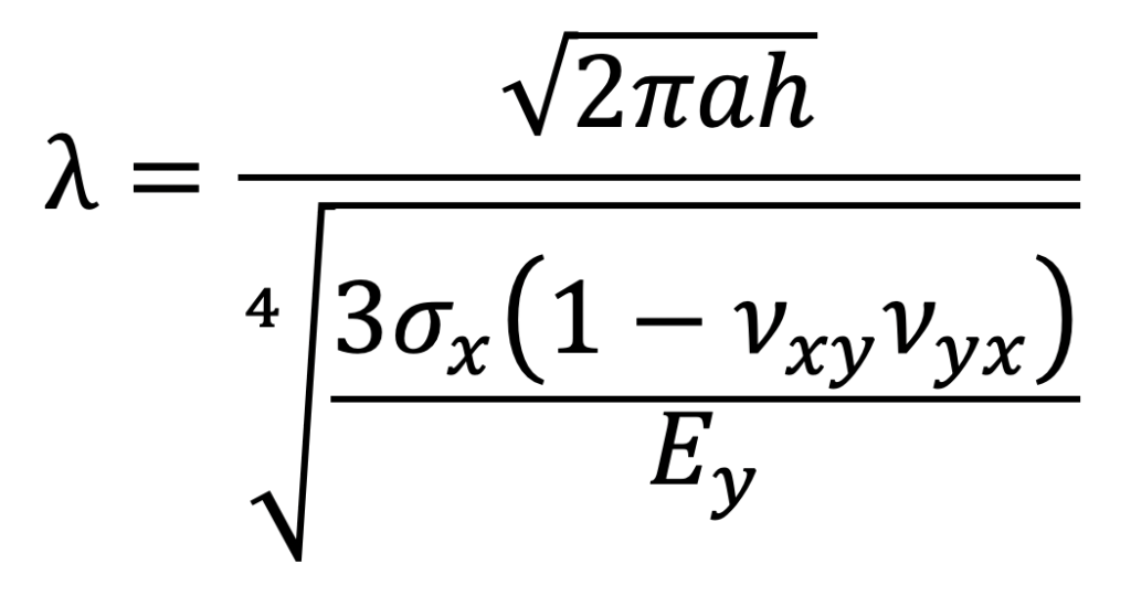

In these equations, λ is the trough wavelength, A is the trough amplitude, a is the span length, h is the web thickness, σx is the web stress in the Machine Direction (MD), Ey is the web elastic modulus in the Cross Direction (CD) and, finally, vxy and vyx are the two in-plane Poisson’s Ratios.
It has been shown in one finite element model [5] that when A/λ ratio is greater than 0.05 (especially greater than 0.075), significant troughs or wrinkles formed in the web.
Using the simulation approach as above, the time history of the A/λ ratio can be calculated for any given web material and actuation scenario. Figure 8 shows the results for polyester film. The very low values for A/λ ratio indicate that the possibility for the tension-induced wrinkles is low.
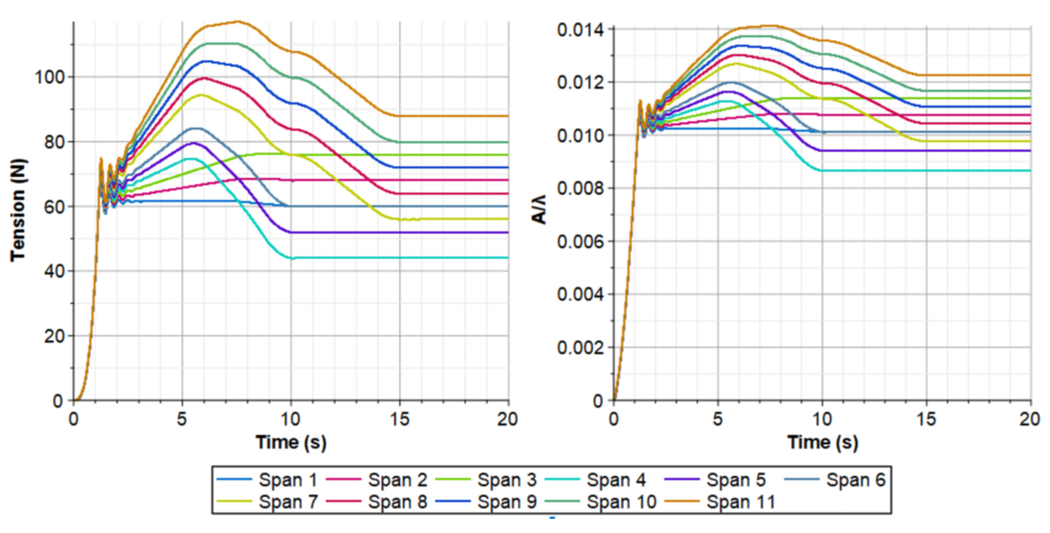
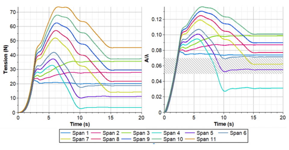
Figure 9 shows the A/λ ratio and its time history for polypropylene nonwoven. For several of the spans at a significant portion of the simulation, the ratio is sufficiently high as to infer that wrinkles may result due to high tension. For this web material, a lower web-tension setpoint would reduce this risk, but due to its lower modulus of elasticity, there also is a risk of not providing enough tension at all times in all spans. Using a simulation to explore this trade-off would be the next step.

Roller Misalignment: The second mechanism to induce troughs in the web is the roller misalignment. The critical roller misalignment angle, θ, can be calculated from Equation 6, where is the shear parameter, is the second moment of the web cross-section and is the area of a beam equivalent that reacts to shear. Additionally, G is the shear modulus, Ex is the MD web elastic modulus and T is the tension in the web. Other parameters are defined above. [6]:
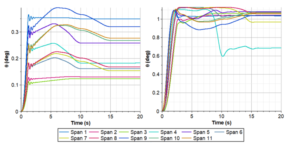
Figure 10 shows the time histories for the two materials and their critical misalignment angles to induce troughs. The polyester web cannot tolerate as high a misalignment angle as the polypropylene nonwoven. Also, the spans that are the least tolerant for misalignment differ between the two materials. The simulation enables the user to focus on the key risk areas for their process and ensure alignment is sufficient where most needed.
Conclusion
System-level modeling and simulation provide a powerful framework to capture the dynamics of R2R processes easily and accurately. This approach has the huge potential to play a central part in the design process, as well as in troubleshooting and improving existing web-handling systems.
References
- Whitworth, David P.D. (1979). “Tension variations in pliable material in production machinery.” Loughborough University. Thesis. https://hdl.handle.net/2134/8427
- Lynch, R. (2017, June). “Optimizing idler diameter.” Paper presented at the 14th International Conference on Web Handling (IWEB), Stillwater, OK. https://hdl.handle.net/11244/322054
- Zahlan, N., & Jones, D.P. (1995, June). “Modeling web traction on rollers.” Paper presented at the 3rd International Conference on Web Handling (IWEB), Stillwater, OK. https://hdl.handle.net/11244/321707
- Nukala, Vindhya (2016). “Buckling of Isotropic and Orthotropic Webs.” Master’s Thesis. Oklahoma State University. https://hdl.handle.net/11244/49128
- Carrle, J., Lange, S., Hamm, R., & Ba, S. (2017, June). “Wrinkling mechanisms of webs with spatially varying material properties.” Paper presented at the 14th International Conference on Web Handling (IWEB), Stillwater, OK. https://hdl.handle.net/11244/322069
- Good, J.K., Beisel, J.A., & Yurtcu, H. (2009, June). “Predicting web wrinkles on rollers.” Paper presented at the 10th International Conference on Web Handling (IWEB), Stillwater, OK. https://hdl.handle.net/11244/321965

Orang Vahid, dir.-Application Engineering at Maplesoft, is the technical lead for the MapleSim Web Handling Library solution. He holds a Ph.D. in Mechanical Engineering from the University of Waterloo and has more than 20 years of experience in system-level modeling, advanced dynamic systems, frictional vibration and control, automotive noise and vibration, and mechanical engineering design. Orang is a frequent invited speaker and has published numerous papers on various topics in engineering design. He can be reached at 519-883-3729, email ovahid@maplesoft.com or https://www.linkedin.com/in/orangvahid/, www.maplesoft.com/engineering/.

Steve Lange is the managing member of ProcessDev, LLC, a manufacturing-process consultancy in Cincinnati, OH. He has more than 35 years of experience in process and material development in the Fast-Moving Consumer Goods (FMCG) industry, retiring as a Research Fellow in Research and Development at the Procter & Gamble Co. Following his chemical engineering education from the University of Missouri-Columbia, Steve developed films, nonwovens, laminates and adhesives with suppliers and the processes to convert them into consumer products. He is a former Chair of the OSU Web Handling Research Center and has expertise in web-handling and R2R converting processes, modeling/simulation, experimental design and data analytics. Steve is a co-inventor on 26 US patents. He can be reached at email: stevelange@processdev.net or www.linkedin.com/in/sjlange/, www.processdev.net.

