
By Chris Davis, head of sales-Industrial Systems, IST America
Introduction
With the current interest in LED-curing technology, many converters are starting to explore this variant of radiation curing either as an alternative to traditional UV or taking the opportunity to review their current curing setups. While the LED platform has some interesting benefits and raises some solid questions about other methods of curing, it doesn’t provide all of the answers. The same can be said for traditional UV systems – or radiation curing as a whole, for that matter.
This article seeks to explore the characteristics of UV, LED and Excimer, their advantages and also the challenges they present, especially for companies looking to transition to a new curing platform.
Incidentally, the reasons for transition also are worth considering in trying to separate the different options and their capabilities and providing answers where there is overlap in the technologies. This is specifically for converters and the “coatings” that are typically applied. It also includes adhesives.
As a point of clarification, “hybrid” is simply a concise term that allows us to define a mixed platform, regardless of which technology is more prevalent in the curing system.
The basis of UV and LED is photopolymerization, where the photonic energy of the UV spectrum triggers a very fast chemical reaction, courtesy of photoinitiators. This reaction creates a grid of C-C bonds that provides the “cure,” and in simple terms, the higher the % of C-C bonds, the “better the cure.” As the chemical mechanism is very fast, it lends itself well to continuous process, such as converting a roll of material, and allows a number of processes to be run on-line, providing production efficiencies.
Differences between UV and LED
To appreciate the differences between the designations of UV and LED, we have to look at the spectra that these systems produce. The modern medium-pressure UV lamp (see Figure 1) produces an output spectra that is roughly in the range of 200-410 nm in the electromagnetic spectrum, where the shorter the wavelength the more energy it has and is good for creating surface characteristics (or alternatively, longer wavelengths have less energy but are good for penetrating coatings), and this is governed by the dopant (additive) used in the bulb. A classic example is the mercury-doped bulb, which produces a UVC-rich** spectrum, and an iron-doped bulb will produce a UVA-rich** spectrum. These different types of bulbs often are mixed in a multi-lamp system to produce a diverse spectrum that a particular coating may require or has an optically challenging color (white or dark colors). Note: Watts/in. is not an indicator of a bulb’s output; this is simply the electrical input into the bulb.
In contrast, the LED array is a type of UV source that produces monochromatic UVA output (see Figure 2). Currently, the common wavelengths are 365, 385, 395 and 405 nm. Sometimes, LED arrays have mixed wavelengths to cover popular formulations that initiate differently or a complex coating that requires a narrow band of UVA. This setup provides an overlap.
In basic terms, the two variables that generally are considered when defining output of UV or LED are dose or energy density (as in mJ/cm²) and intensity or peak (measured in mW/cm²) in a given band (UVC, UVB or UVA) or wavelength for LED. Dose is the amount of energy available for cure and is time- (speed) related. Intensity is how “bright” the output is perceived and becomes important with heavier coatweights or opacity (as previously mentioned) where the energy needs to be driven through the layer to ensure cure all the way to the substrate. Distance from the emitting source also will have an effect on both values.
As the radiation-curing equipment has to work in tandem with UV-reactive formulations, an understanding of the chemical mechanism also will affect the type of emitting source and the environment in which the reaction takes place. There are a number of technical coatings that suffer from oxygen inhibition, which basically means that the presence of oxygen stops the reaction from propagating correctly, and thus the media does not cure properly. In this case, inerting chambers (see Figure 3) are used under the light source, and typically these are filled with nitrogen (with closed-loop control). A good example would be free-radical silicone.
Grouping UV and LED together, these two curing technologies do offer some immediate advantages over aqueous and solvent-based coatings. A quick summary would include:
- UV and LED lampheads are relatively compact and easily installed into existing lines or new machinery. Removing long and costly ovens is an immediate cost benefit.
- As there is no mass transfer, the thickness of the UV or LED coating applied is the cured thickness. This simplifies the process and brings cost benefits.
- There are no VOCs with UV or LED, which removes the operational complexity in the plant and, of course, costs.
- Both UV and LED are based on solid-state technology, which lends itself well to monitoring and real-time measurement, providing valuable production data that in turn leads to predictable processes and stable output.
Separating UV from LED, we can take a look at the relative advantages and challenges.
UV
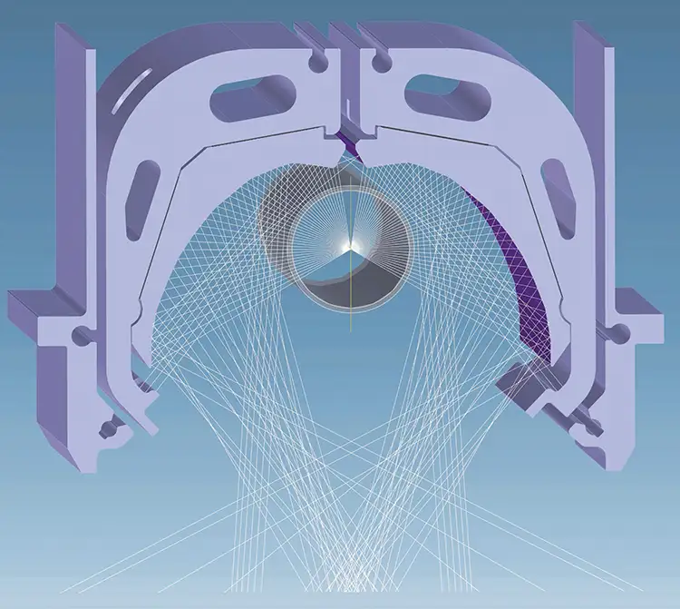
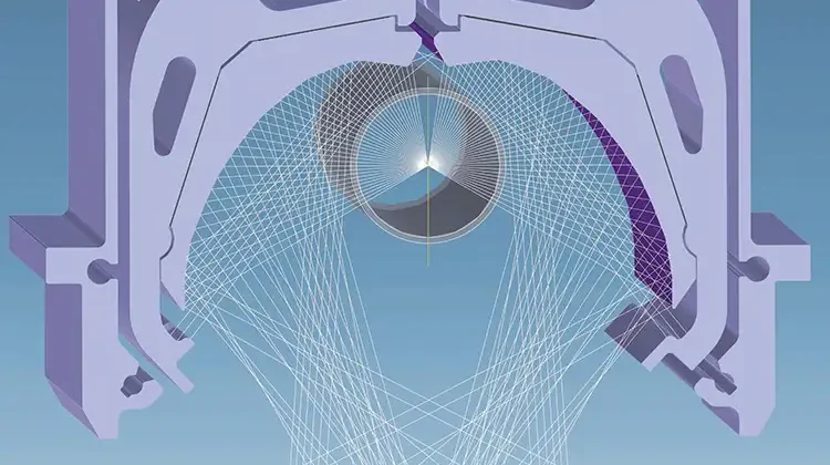
As previously mentioned, a UV lamp has a broad output spectrum with the emphasis being determined by the dopant. As a corollary to the UV output, an arc lamp also produces visible light and infrared (IR) heat, which usually is managed by cooling channels in the lamphead. As a bulb emits in 360°, only about 35% of its energy is incident on the substrate. The rest is reflected and focused by highly engineered reflectors designed to let the longer wavelength IR go through into the cooling channels (see Figure 4). The reflectors allow UV lamps to project their energy at a reasonable distance from the bulb. Although the output spectrum has a bias given by the dopant, it still will produce energy in the other UV bands, albeit at a lower level.
UVC often is used to produce surface characteristics (remembering the short-wavelength / high-energy combination). This could be mechanical resistance (superior to other coatings), release characteristics, and decorative and functional finishes (varnish is a good example). The number of UV-curable coatings currently is much higher than what is offered for LED, although it should be noted that there is ongoing research.
The heat that is produced in parallel with the UV output can be a challenge in how it is managed. Although the lamphead itself is cooled with water channels (to act as heat sinks), heat still is transferred onto the web, which for some substrates (thin films, extensible films, shrink materials) is problematic. In most mid- to wide-web installations, the UV lamps usually are mounted over chill drums to help manage the thermal load and lend stability to the web.
For converting applications, a water-cooled system usually is selected, as it has a higher output than air-cooled and controls the IR much more efficiently. Along with the lamphead and mounting hardware, a heat exchanger (or chilling unit) usually is provided, as well as exhaust-air infrastructure (hoses, plenum and fan) and electrical/control cabinets – all of which add up to a reasonable footprint and electrical load.
When a UV system is in production mode, the lamps are on and producing output. If the line needs to stop, the lamps will sit in standby mode so they are, in effect, in the right operating condition to start running production again as needed. This standby mode also requires electricity. If a lamp is shut down (say, for an e-stop), it will take two minutes to come back to production-ready mode. All of this has a cost.
Another point to consider with UV lamps is that the bulbs and reflectors degrade over time and need to be replaced, so there are consumable costs. Although, most bulbs will run over 3,000 hrs before needing to be replaced, and reflectors well over 12,000 hrs, it still is something to consider in the final analysis. Note: Although outside of the scope of this article, mercury-doped bulbs and their disposal are much less problematic than often portrayed and are widely misrepresented.
A final point on the capital expenditures of the UV platform: When the output (dose especially) is matched, UV systems generally have a much lower acquisition cost than LED.
LED
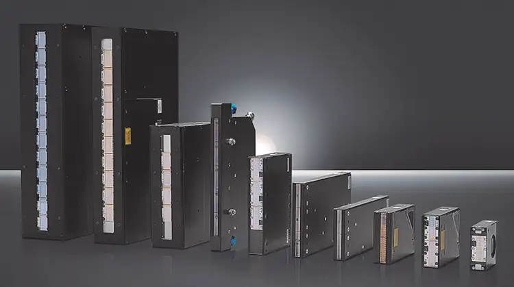
As LEDs produce UV output via a different mechanism, they do not produce IR heat at the emitting window. As the platform is electronically based, they can be switched off and on as needed and do not need to be in standby mode. The LED arrays are usually more compact and much less complex than their UV counterparts.
LED modules also offer considerably longer lifetimes, with 20,000-25,000 hrs being relatively common (after which they need to be replaced). Unlike a UV bulb, where the full length of the bulb is irradiating, a LED array can switch off modules not in use to cater more efficiently to different coating/web widths. In addition, LED doesn’t produce ozone, and therefore the hoses, plenum and fan that the UV requires are not needed. Besides simplifying the whole architecture of the system, LED offers many cost-saving opportunities, not just on power consumption but in the production process itself.
Certain formulations are ideal for LED as the longer wavelengths allow for heavier coatweights and difficult-to-penetrate (for UV) media. Although the photoinitiator species is different than UV, the principle is the same. As a point of interest, LED arrays can impart heat onto the web, if the coating doesn’t absorb all of the emitted energy.
A Rule of Thumb in LED curing for converting is that systems up to 16 W/cm² output are air-cooled and over 16 W/cm² tend to be water-cooled. The cooling is for the electronics and drivers needed for the LEDs themselves, and this produces internal heat, which needs to be managed. Similar to UV, the higher the output, the more heat needs to be managed, but here it is in the housing and not web-facing.
Although LED technology offers a lot of benefits, there are some drawbacks that need to be considered before making a transition. Many converting formulations are not available as LED-curable, and those that are don’t always offer the same end result as a conventional system. As they have evolved, LED-array outputs have increased, but they still suffer from having to have the substrate relatively close to the emitting window, which can be a challenge in some converting lines. LEDs have good longevity, but this can be influenced easily by poor maintenance, unsuitable working conditions and poorly calibrated electronics. Therefore, housekeeping and maintenance need to be clearly defined and regularly undertaken.
When compared to UV, an output-matched LED system has a higher price tag. It will have lower operating costs as it doesn’t have consumables, and it can be switched on as needed. However, the production cycles need to be carefully evaluated to ensure an accurate comparison. As an example, a short-run line that has many stops and makereadies will have a different calculation than a line running 24/7.
Enter the Excimer
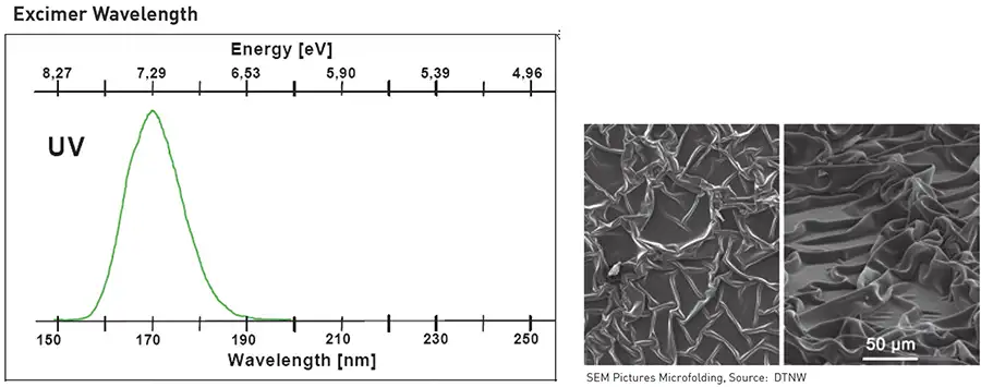
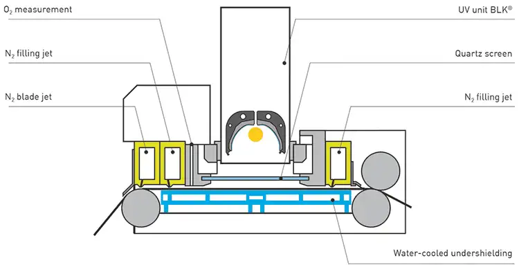
Excimer is a specialized emitting source (see Figure 5). It is monochromatic at 172 nm and, therefore, produces a hammer of energy to the tune of 7.4 eV, which is high enough to break the bonds in hydrocarbons and create microfolds in the surface of coatings (a few microns thick). This offers an alternative to expensive formulations that create matte effects, as the light is diffused when it hits the microfolds. In breaking the bonds of hydrocarbons, Excimer can be used for surface cleaning (prevalent in display manufacturing). That same energy also can be used for surface modification to change the energy characteristics. Excimer can be seen as more of a modification tool as opposed to a curing method. It is an augmentation to radiation curing.
One disadvantage of Excimer is that nitrogen is needed to create an inertization chamber (devoid of oxygen), and this adds to the cost of operating the technology. Depending on the viscosity and opacity of the coating, this may require a pre-gelling unit to achieve the matte required, meaning additional capital expenditure. Another point to consider, Excimer bulbs usually run up to 1,500 hrs and are relatively expensive to replace, so the operating costs of Excimer must be carefully considered.
Excimer (width-matched) has the highest capital expenditure out of all three systems, but there are distinct cost savings in the right production environment, as it is an alternative to multiple costly coatings and surface modifcation.
Hybrid radiation curing
As illustrated, each system has clear advantages and can be combined (more and more frequently) to provide a hybrid platform that gives an ideal outcome, as opposed to a compromise or change in formulation that can be time-consuming and costly to implement. This offers converters a much wider process window and, therefore, their customers a superior product at a competitive price. Converters also can take on new market/product demands by retooling their curing operation.
A good example of all three technologies in one platform is in the vinyl-flooring industry where the desired optical effect is a matte, and the final surface finish has to be very durable. Traditionally, this was cured via UV using different bulb dopants to create a pre-cure mattifying effect (with UVA) and then a final cure to give the surface the hardness and resistance characteristics (with UVC). Typically, these lines are very long.
The alternative is to use an LED as a pre-gelling unit prior to the Excimer unit, so the viscosity of the coating is ideal for micro-folding. It then goes under the Excimer to create the matte effect and then under a UV lamp with a mercury bulb to give it the final surface finish. To switch from matte to gloss, simply turn off the Excimer unit. Only one formulation is required for this line, and it reduces the production footprint required to 20%.
In this example, the UVA source can be replaced with an LED, and the final cure still is with UV. This combination of LED and UV is generating a lot of interest as it is relatively straightforward to retrofit.
Conclusion
There is no perfect curing platform. The technical requirements need to be defined very clearly in terms of output and spectrum. This generally is application-driven and formulation-based, and ultimately the capital-equipment and operating expenditures need to provide a compelling argument to make a change or augment existing technology. Formulations and equipment are both being constantly refined and part of the discovery phase for suppliers is looking toward future needs and ensuring that the technology is open-ended (no costly retrofits) and that the formulations offer characteristics for developing markets.
**The UV spectrum is usually divided into UVC, UVB and UVA. These are generally accepted as UVC 200-280 nm, UVB 281-340 nm and UVA 341-410 nm.
Chris Davis, head of sales-Industrial Systems, IST America (Shorewood, IL), is a degreed mechanical engineer who has worked in the converting industry since 1993. He joined IST in 2015 with areas of expertise in converting and industrial UV/LED applications. Davis has authored several articles and is a presenter at technical seminars. He can be reached at 630-561-2024, email: chris.davis@usa.ist-uv.com, www.ist-uv.com.