By Dave Rumson, slitting educator and consultant
Editor’s Note: This digital edition now contains a correction on page 76 from the author. We apologize to our readers.
Introduction
Why do we trim slit webs? To paraphrase the late Professor Erwin Cory, “That is a two-part question. Why? is a question that has plagued mankind since time immemorial.” Secondly, do we trim slit webs? That answer is yes.
One of the reasons we trim slit is to remove baggy web ends from certain extruded polymer materials that tend to have a disproportionate edge thickening. Other webs may have excessive lamination or adhesive-coating issues that must be removed so that we have a clean roll face on both ends and an acceptable roll shape. Also of importance is that we always want to establish an accurate full-roll width so that precision-slit individual rolls will meet required-width specifications.
In all aspects of the trim-slitting process, it’s paramount to know your material’s characteristics, the dynamics of the web-fracturing process and to match the slit trim to the removal equipment that meets your needs.
Know your material’s characteristics
The important material characteristics are its density; is it soft or hard? Its thickness; what type and size knives are needed? Its elongation and memory; does it stretch permanently or return to its original shape? Is it stiff and brittle with likelihood of splintering or creating a jagged edge? And does it have abrasive or adhesive coatings that might negatively affect the life of knives or trim-collecting equipment? Then there’s the web-fracturing aspects of your material. What are its Yield Strength, Ultimate Strength, Flexural Strength, Tensile Strength, Compressive Strength and Shear Strength?
Slit trim widths from 0.5 to 2.0 in. (12.7 to 50.8 mm) are more common and always are web material- and web pull-tension-dependent. But keep in mind that any trim width below 1.0 in. (25.4 mm) or from a more delicate web material will require much tighter process control to meet production goals.
And to meet those production goals, the dynamics of roll making and slitting relating to trim removal and collection of your specific material(s) must be well understood. These dynamics include proper control of the Trim Slitting Fracture, Trim Support, Pull Tension, Travel Direction and selecting the best type of Trim Collection Equipment.
Choose the correct slitting method
As we know, the three major web-slitting methods are Razor, Crush and Shear, and the choice of which to use directly relates to, as mentioned, the web material’s characteristics, the operating dynamics and roll-quality specifications.
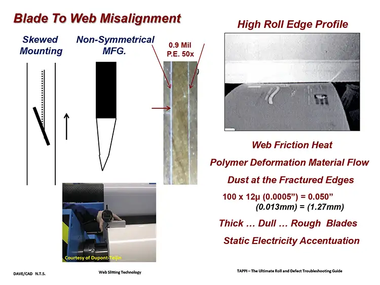
Razor slitting can provide the cleanest web-fracture edge for thinner and less dense materials but has a shorter operating life. The more commonly used blade is the Double Bevel, with thicknesses ranging from 0.004 in. (0.101 mm) to 0.125 in. (3.175 mm). Ensure the blade is not mounted misaligned (skewed) to the web path for two reasons. First, this prevents potential blade breakage from Cross-Machine (CD) web-shifting forces. Second, it lessens web contact friction that can create the High Roll Edge Profile slitting defect. Be aware that a blade that is manufactured with non-symmetrical grind or honed angles also can create the High Roll Edge Profile slitting defect (see Figure 1).
Razor slitting generally is limited to running at web speeds up to 1,000 fpm (304.8 mpm). Speeds above that to increase production quickly can reduce useful blade life with a higher possibility of creating a poor-quality, web-fracture edge.
A very interesting comment on this came during one of my past Web Slitting Technology (WST) classes. When I mentioned the Razor slitting 1,000-fpm speed maximum, an attendee said his company razor-slit at 2,000 fpm. With further discussion, he pointed out that it has a roll-to-roll (R2R) slitting operation and, after every “Mother Roll” is totally unwound, the company changes all the lower-priced razor blades during the reloading of the next roll to be unwound. Seems like there’s always a different way to do things.
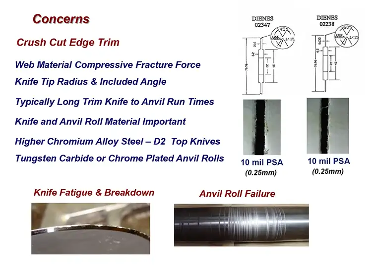
Two major Crush Cutting finished-roll quality factors are the knife’s thickness and tip shape. The thinner the knife and the smaller the tip radius, the cleaner the fracture with less slitting dust created, thus also lessening the chance of the High Roll Edge defect. But Crush Cutting with its highly compressive contact force can severely stress the knife-tip and anvil-roll surfaces. It is not uncommon for the knife-tip material to break from overloading or fatigue and then mechanically harden above anvil-roll hardness. Then anvil-roll gouging starts if it’s left in the machine. The trim slitting position is more commonly set in the same location and is more vulnerable to gouging. Knowing the limits of knife and anvil life is extremely important. Don’t ignore bad crunching sounds (see Figure 2).
One way to potentially benefit from longer anvil-roll life, but with a higher level of cost, is with slitting systems that very slowly move the anvil roll back and forth a short distance in the Cross-Machine (CD) direction to greatly extend Anvil Roll life.
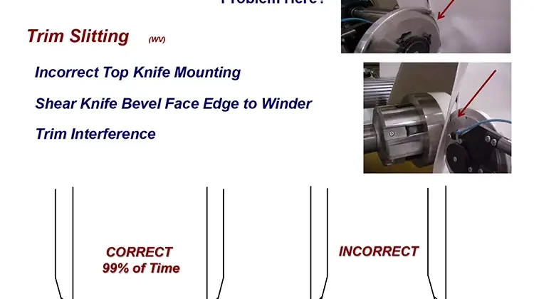
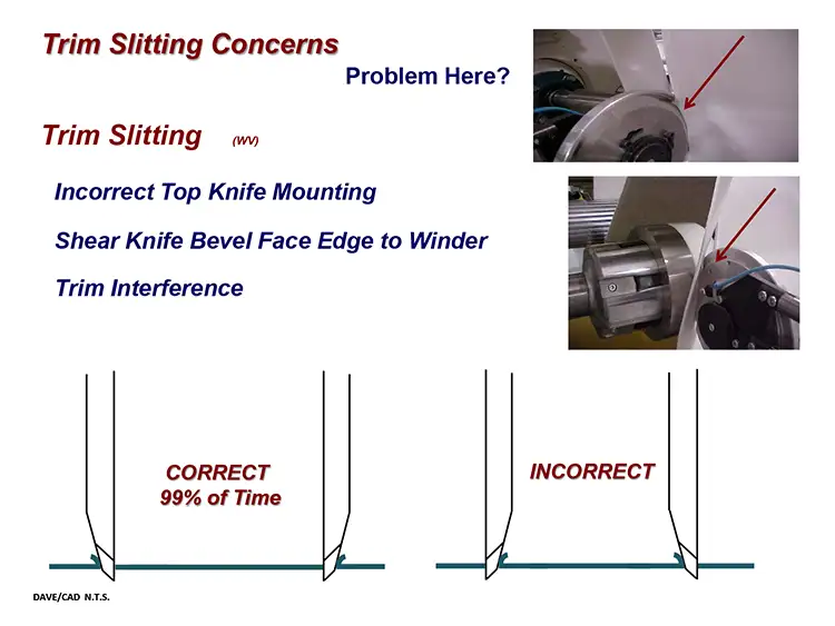
The common Shear Slitting trim rule is that the top-knife’s bevel side should face the trim strip, with the non-bevel side facing the winding web. The non-bevel side creates less web-edge fracture damage by not deflecting the web away from the web path.
The bevel side does create a CD stress to the narrow trim strip though, pushing it away from the web path direction, so some special control care is needed here. When discussing this in my WST class, I show a photograph of a tangential web-path slitting section with an incorrectly installed shear knifeholder. The shear angled, top-knife bevel-face is positioned to contact the full web (see Figure 3).
During one class, an attendee mentioned that, more often than not, his company “did” set the trim top-knife bevel toward the full roll, not the trim, and slit widths to 0.25 to 0.50 in. (6.35 to 12.7 mm) at 4,000 fpm (1,217 mpm). Now this was very interesting. Now this was very interesting. The company did its own high-precision, in-house knife re-sharpening and, after many empirical studies, established the best knife angles for both top and bottom knives used for a variety of web materials. Because the top knife is tapered, its thickness increases at the web Cut Point when its diameter lessens during re-sharpening. The knife also is reground to its original thickness.
Steady as she goes
When the trim-slitting fracture is made, the web must be supported on a Shear bottom knife, a Crush anvil roll or a grooved Razor roller to reduce potential for web flutter, unless you’re In-Air Razor slitting. Then, maintaining the proper pull tension control across both the in-feed and exit slitting zone rolls is extremely important.
Low tensile-strength material trim slits should immediately travel over a driven, web speed-matching exit roll on the way to collection.
Higher tensile-strength trim materials can possibly be directed quickly into a trim suction tube. To ensure a smooth takeaway, the trim collection system’s winding pull tension or trim duct-suction levels should match the winding tension at the slitter. Excessive pull tension increases the possibility of the trim breaking. Insufficient tension can cause trim flopping, possible trim foldover onto the continuing finished-roll web and increased slitting dust. This especially is important when slitting with an off-line machine that is accelerating and decelerating with every roll change.
A few years ago, during a client plant visit, I saw the Trim Strip bouncing erratically right after the Cut Point fracture. There was zero trim support and pull tension. The client was letting the trim fall to the floor, which I immediately pointed out as a problem.
The material was a low-temper foil with a very hard, wire-like material adhered across the web about every 12 in. (305 mm). The slitting system easily fractured the foil but did not easily fracture the hard wire. A strong “fracture bounce” of the web resulted each time the wire broke.
Later, in a conference room meeting and after someone mounted a real-time camera on the machine to watch the trim fracture right before our eyes, the trim bounced over and onto the winding web, and the machine shut down. My point was made.
Before a trim slit is made, the full web has a single web tension pull profile. It’s important that the web is flat, taut and free of wrinkles that might cause looseness and fluttering at the Cut Point. Some webs may require a spreader roll before the slitters to reduce or remove any wrinkles. Be aware though that if overset, “pre-slit spreader rolls” and other factors can create excessive CD stresses that may result in a “cracked edge” at the slitting locations. According to web-handling expert Dr. David R. Roisum, Cracked Web Edges cause more web breaks than any other web defect.
Collecting all that trim
There are a variety of Trim Collection Methods, and it’s very important to match your web material’s characteristics and needed operating dynamics to the proper collection method.
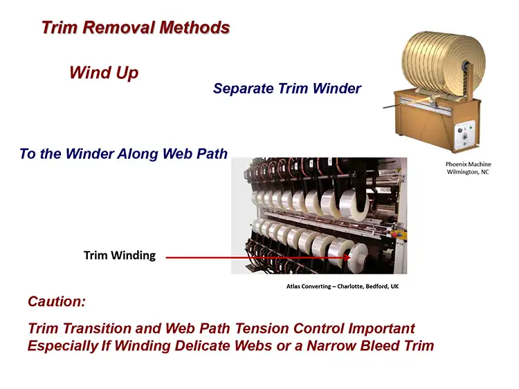
One way to collect trim is to wind it into a roll for easy machine removal. This could be with a separate, independent small winder that receives the trim on a path different from the rollmaking web path. Another wind-up method is to send it along to the finished-roll winding machinery to wrap up on its own core, alongside the finished rolls. One caution with this method is that it could be tricky to maintain the proper tension control as the trim slit journeys through the machinery, especially if winding delicate webs or multiple narrow-bleed Trim Slits (see Figure 4).
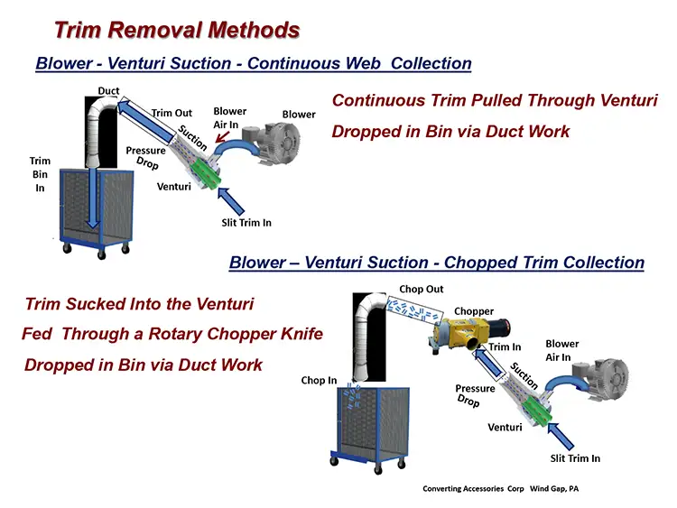
The more common trim collecting systems use an air blower and Venturi to create a pressure drop with suction that can pull a long, continuous trim strip via ductwork to a collection bin. Another blower Venturi collection system sucks the trim into a Rotary Knife chopper that cuts it into small pieces. These pieces then are transported via ductwork into a collection bin or, in certain cases, directly into a film extruder’s in-feed section. Chopped pieces can be transported longer distances than the continuous trim slit (see Figure 5).
For both of these trim-suction systems, it’s critically important to control trim Pull Tension to prevent breakage during transport. Depending on the web Tensile Strength, the trim suction intake should be as close as possible to the slitting Cut Point. A steady Venturi-suction velocity can work for certain materials and 24/7 nonstop rollmaking. But a varying velocity may be needed to match the varying winding-web speed and web tension-level changes in a R2R-slitting operation. Most of the time, the Pull Tension should be the same as the finished roll-winding tension. Excessive tension can cause a ragged slit edge or potentially trim-slit breakage. Too low a tension pull can cause trim flutter, excessive slitting dust or a trim bounce that also can lead to breakage.
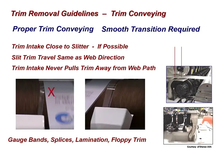
Note: It is important that the Trim Collection never creates an axial pull stress on the trim. This increases the potential for a trim break (see Figure 6).
Keep process and web factors in mind
There also are more Trim Slitting guidelines relating to the web material and specific process factors that may satisfy special requirements for the trim-handling equipment.
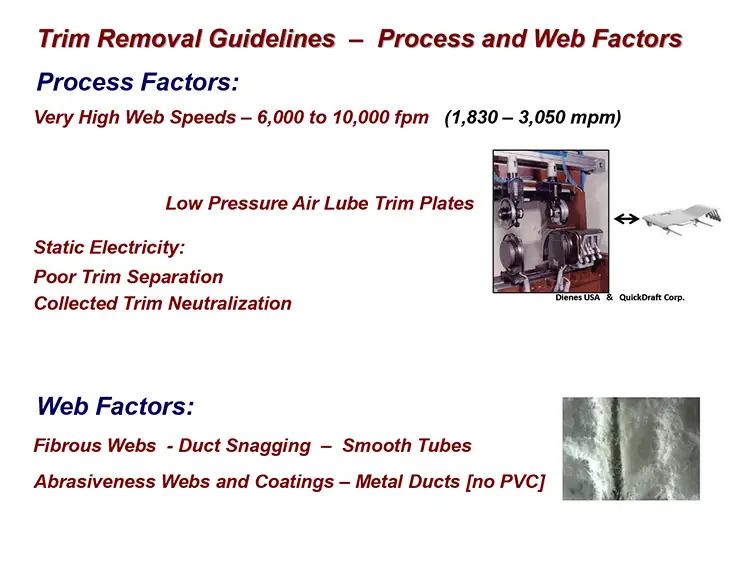
Handling trim running at very high speeds (6,000 to 10,000 fpm [1,380 to 3,050 mpm]) may require a special, low-pressure air plate to stabilize the trim by slightly lifting it to reduce dragging.
Fibrous webs will find and snag on any protruding, internal ductwork unevenness. Smooth internal ducts are key to prevent accumulating blockage. Abrasive or abrasive-coated webs will require metal ductwork because PVC ducts will wear away faster (see Figure 7).
You might be shocked to hear this, but static electricity can prevent you from having a clean trim-slitting fracture and, of course, a bin full of statically charged web trim is dangerous…to say the least.
Then there’s adhesive-web slitting that usually exposes the stickiness that creates a totally different trim-collection problem. A Venturi suction-pulled, continuous adhesive web sticks to itself and has much more potential for clogging ductwork than a chopped adhesive trim. And the chopped adhesive trim usually can be conveyed further than a continuous web.
There are certain adhesive trim-slitting caveats, though. Internal chopper components and ductwork may require a low-stick Teflon or Plasma coating to be effective but with a higher expense. Some systems have benefitted from a powder being applied to the ductwork, but this can be messy and need regular cleaning and refill scheduling. And, again, all these factors depend on the web’s properties and adhesive strengths.
Most trim-removal equipment suppliers offer laboratory-like trials on short lengths (50 to 100 ft [15.24 to 30.48 meters]) of your material to define the best trim-collection method. The AIMCAL SourceBook is an excellent supplier reference (Go to www.aimcal.org, click on “Resources.”).
A summary of reasons Trim Slits can be lost during collection include, as previously mentioned, misdirection of trim travel to the intake duct or the winding device, too little or too much suction or winding pull-tension force, varying suction forces from winder speed changes, web axial shifting in the Slitting Zone, excessive travel distance of unsupported trim and clogged ductwork.
Trim systems need to be kept clean; don’t duct this responsibility.

Dave Rumson has 14 years of experience as a slitting educator/consultant and 30+ years of roll /shaft handling, unwind/rewind equipment and web-slitting experience. The past 20 years include 10 years with Dienes USA and Sigmala, Ltd., the latter having developed a computer/servomotor-controlled shear knifeholder. For 25+ years, Dave has developed and conducted technical presentations for CEMA, AIMCAL and TAPPI. He currently serves on the Technical Advisory Panel, its Web Handling Committee and writes the “Cut Points” Q&A column for Converting Quarterly. Dave also manages the 1,500-member Slitting Community Group on LinkedIn. He can be reached at 860-256-5658, email: drumson@maine.rr.com or www.drumson.wordpress.com.

