
By Clarence Klassen, P.Eng., KlassENgineering, Inc.
Editor’s Note: This is the first technical article in a two-part series discussing the commissioning of a web-handling line. Part 1: Dry Commissioning discusses the individual drives without the web. Part 2: Wet Commissioning discusses final commissioning of the line while running with the web and starting a process, such as coating.
Introduction
Drive systems for web handling are among the most complicated of drive systems. The drive system is used to control speed and tension in multiple tension zones and with a number of very different machine sections. The driven machines often are supplied by several manufacturers. Drive performance following commissioning and tuning of the drive system depends heavily on the drive technician, machine builder(s), customer management and customer operators. We expect the drive tech to coordinate personnel safety, ensure machinery is protected, tune the drives, configure communication networks, modify the Operator Interface (HMI), replace failed components, train operators and – finally – tune the tension regulators.
How does the drive technician plan and execute the commissioning of a web-handling line drive system in an effective, timely and cost-efficient manner? A general methodology for commissioning the web-handling drive system is presented. The rationale for drive commissioning, tension/dancer calibration, drive tune-up, dry-line commissioning and wet-commissioning activities will be presented. Emphasis will be given to the unwind and winder drives. Finally, a sequence of tuning the multiple tension-zone regulators will be presented.
Definitions
For a better understanding of the dry and wet commissioning process, the following seven terms are defined as they apply to the task.
- Drive – Adjustable Speed Drive (ASD) with its motor, wiring, tachometer (encoder), speed reducer, coupling and shafts.
- HMI – Human Machine Interface (Operator Interface). This may be a computer screen, or pushbuttons and meters (or a combination of these elements).
- Drive master controller – a computer or PLC programmed to coordinate a system of drives and HMIs to process the web.
- Start of commissioning – Equipment is on-site, installed, with wiring complete. Drawings are complete. Software is complete – Drive Master, drives and HMIs. Motors are coupled to their loads with guards in place. Electric, water and pneumatic services are available.
- Multi-section tension zones – Where there are n driven traction points, there will be n-1 drive or tension zones. Two driven traction points establish one tension zone.
- People involved in the project – Drive Tech ($2,000-$3,000/day PLUS expenses PLUS rework), Machine Builder representative and End User (operators, project management, process engineer, safety committee).
- Watcher – person at the machine section being commissioned near an E-Stop button with constant communications to the drive tech.
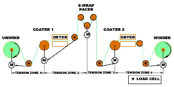
As an example, we will consider a web-processing line with Unwind, Coater 1, S-Wrap, Coater 2 and Winder (see Figure 1). For discussion, the unwind and winder drives modify motor torque to regulate tension. The coater drives modify speed to regulate tension. Five driven traction points form four tension zones on this line. The unwind and winder tension regulators will use load cells to vary torque. The coater-tension regulators will use load cells to vary speed.
Pre-commissioning
Pre-commissioning occurs shortly after installation of the equipment and will require power on but will not require operators, rolls of product or threading of the line. The Drive Tech must plan and execute the steps listed in the pre-commissioning checklist below. This equipment will be discussed from the viewpoint of the Project Management team with tasks given to the Drive Tech.
Pre-commissioning checklist:
- Gather drawings and speak with the drive system control engineer.
- Prepare a pre-commissioning plan and timeline.
- Verify that all firmware and software revisions are compatible over the system.
- Verify wiring is complete and correct.
- Check out the I/O (10 mins per input/output point using two people).
- Check out all communications to drives, other PLCs and the plant network (This often is a sore spot requiring days).
- SAFETY – Validate (using a checklist) all of the Safety circuits– Emergency Stops (E-Stops), interlocks, safety relays, safety PLCs.
- Check out the HMI (communications and programming software setup).
- Setup Historical Trending for critical signals – trending should be ready for commissioning, not after problems occur.
- Prepare a logbook (or computer log) for the line.
- Calibrate all load cells or dancers.
Commissioning individual drives
Much of the drive commissioning can be done as sections of the line become available. At this stage, commission individual drives as far as possible. Each drive will require 1 to 8 hrs. The winder and unwind are more complicated than other drives, so these take up to 8 hrs. Refer to the individual-drive tuning checklist and timeline below.
For each driven section:
- SAFETY – Use Danger tape to keep people away; establish constant radio communication with a machine watcher.
- EQUIPMENT – Consider potential equipment damage (reversing against a coater blade, loss of lubrication, over-temperature, under-temperature, over-pressure).
- Auto-Tune the torque loop (all tuned for the same response – see manufacturer instructions but about 300-500 radians/sec. Record the response with high-speed trending.
- Auto-Tune the speed or velocity loop (all tuned for the same response – suggest 1-5 radians/sec). Record the response with high-speed trending.*
- Check jog, jog reverse, thread, slow and run operation.
- Run each section individually at the design speed from the HMI.
- Check for vibrations, noise, rubbing, heating.
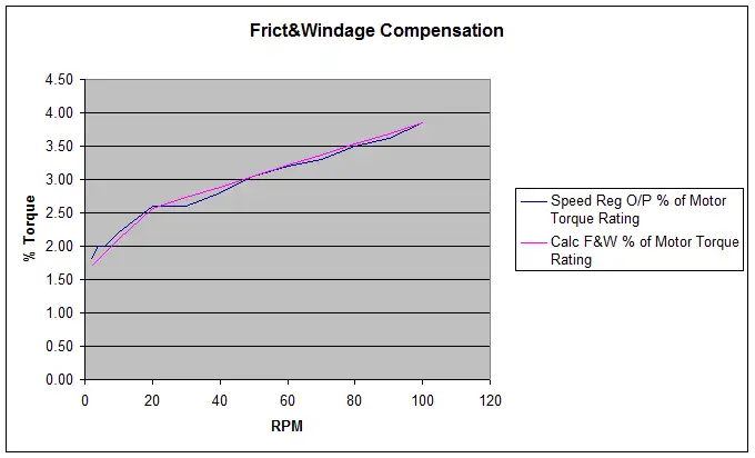
- Verify the torque (internal to the drive). Friction compensation may be set at this time (see Figure 3).
- Safely use a hand tachometer to verify that speed is close (within 1%).
- Preserve backups of the setup data for all programmed devices (copy for the Drive Tech, local and archive copies for the End-User plant).
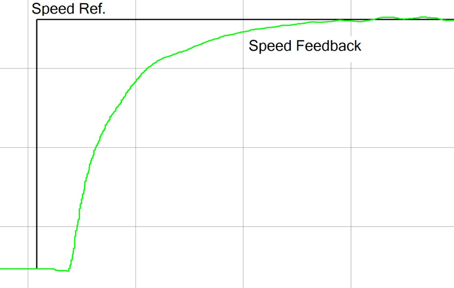
*The least responsive speed loop generally is limited by the section with the most backlash in its couplings or the highest inertia. This often is the unwind running an out-of-round roll or may be limited by a large inertia section, such as a cast roll or drying cylinder. The best practice is to save a step-response trend for the speed regulator in each drive in the line logbook or file as shown in Figure 2.
For each Unwind and Winder, begin by using an empty core and then a full-sized roll.
The checklists follow:
- Load an empty core.
- Freeze the diameter at core diameter.
- Disable the tension regulator.
- Disable the web-break detector.
- Disable the diameter calculator.
- Auto-Tune the torque loop (all tuned for the same response – see manufacturer instructions, but about 300-500 radians/sec. Record the response with high-speed trending.
- Auto-Tune the speed or velocity loop (all tuned for the same response – suggest 1-5 radians/sec). Record the response with high-speed trending.
- Check jog, jog reverse, thread, slow, run operation.
- Run the unwind and master drive at half speed (fpm or mpm) in speed regulation. Safely use a hand tachometer to verify that speed is close (within 1%).
- Check the motor volts using the Volts vs. RPM curve supplied with the motor.
- Examine the diameter calculator. Even though it is disabled, the calculation should be active and the core diameter should be calculated.
- Run up to design line speed. There should be no unusual vibration or rubbing.
- Run down to 0.5% of design line speed in speed regulation. The drive must run well at this low speed; the line is threaded with motion.
- Fill in a chart of running torque vs. RPM. This will be used to curve-fit a friction and windage function. Running torque can be torque or speed regulator output within the drive. See Table 1.
- Populate and enable friction and windage compensation. See Table 1 and Figure 3.
- Run the line with the S-Ramp. Set the Inertia Compensation for the empty core (fixed inertia). When set correctly, the output of the speed regulator should not deviate during a speed change.
- Load a full roll. Tape the web to prevent unwinding or expanding.
- Preset the diameter at the actual diameter.
- Disable the tension regulator.
- Disable the web-break detector.
- Disable the diameter calculator.
- Auto-Tune the speed or velocity loop (all tuned for the same response – suggest 1-5 radians/sec). Record the response with high-speed trending.
SAFETY – Prevent overspeeding a large roll. - Select speed-regulator parameters between those auto-tuned for the core and large roll. Note the unwind-speed regulator most often is used at large diameter, and the winder-speed regulator most often is used at core diameter.
- Check jog, jog reverse, thread, slow and run operation.
- Run the unwind or winder drive at half speed in speed regulation. Safely use a hand tachometer to verify that speed is close (within 1%).
- Check the motor volts using the Volts vs. RPM curve supplied with the motor.
- Examine the diameter calculator. Even though it is disabled, the calculation should be active and the roll diameter should be calculated.
- Run up to design line speed. There should be no unusual vibration or rubbing.
- Run down to 0.5% of design line speed in speed regulation. The drive must run well at this low speed; the line is threaded with motion.
- Run the line speed up and down with the S-Ramp. Set the Inertia Compensation for the full roll (varying inertia). When set correctly, the output of the speed regulator should not deviate during a speed change.
- Load a core and recheck the speed regulation and inertia compensation for the core.
- Preserve backups of the setup files.
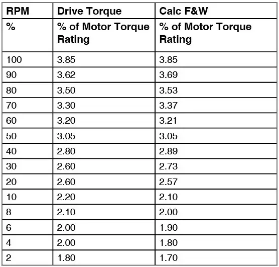
The Friction and Windage data chart for a winder with a large gear ratio will have values similar to those shown in Table 1.
The friction and windage from the chart above can be modeled (curve fitted) as Equation 1 Friction Model as a Function of RPM (see below). The model closely matches the measured friction and windage. Don’t spend too much effort on the friction and windage model. Friction changes with temperature and will change over months of operation.

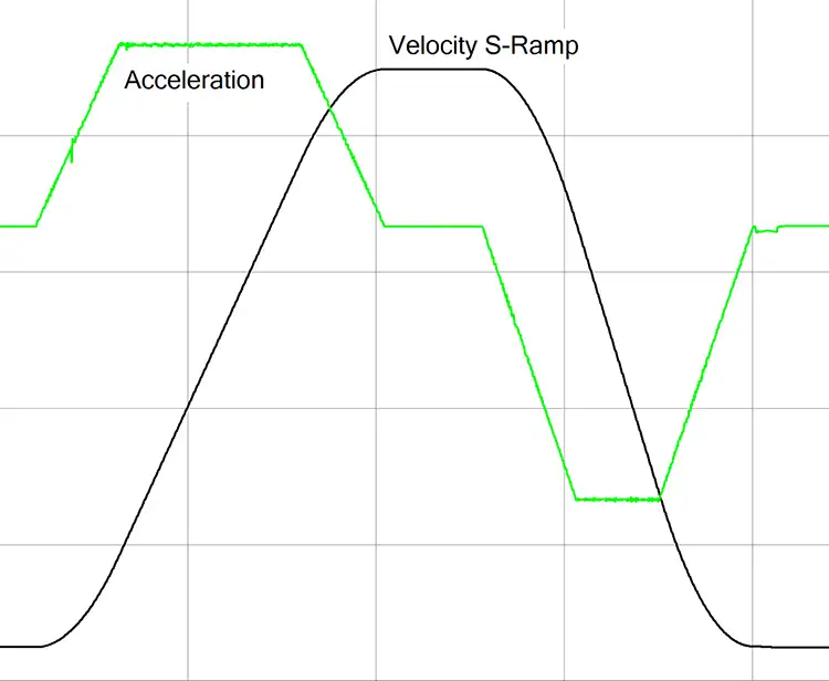
To coordinate all drives while changing speed with minimal tension upsets, an S-Ramp is recommended. This reduces jerking the web at the start and end of a speed change. See Figure 4 for the S-Ramp Speed and Acceleration. The acceleration ramps up slowly to a constant value and then holds at the rated acceleration. The speed increases following an S (sigmoid)-shaped curve.
Dry Commissioning – without web
A lot can be learned by running the entire line without threading the web. It will be necessary to tape off the entire line for safety. You must keep the welders, painters and other trades out of harm’s way. Below is a checklist to dry-run the entire line. Establish constant radio communication with machine watchers.
More people critical to the project, including mechanical equipment suppliers, become interested at this stage. They can watch, comment and stop the line, but the line is not yet ready for the mechanical calibration and commissioning of calenders, printers, nips, laminators or treaters.
Steps to dry-run the entire line:
- Remove Danger tape from the line
- Put cores in the unwind and windup.
- Disable web-break detectors, all tension regulators and torque mode for the unwind and winder. Preset and disable unwind and winder diameters at the core diameters.
- Set the line speed to zero FPM or MPM and all tension setpoints to 0 PLI (N/m).
- For tension regulators in the middle of the line, enable the tension regulators one at a time (assuming tension control through speed). Increase the tension setpoint slowly to full value. Verify that the drives increase in speed by the authority of the tension regulator (1 to 2 to 5% of design speed). Note: Driven points upstream of the master must slow to increase tension.
- SAFETY – Perform and document all safety interlock and E-Stop validation tests for all drives. The plant safety committee should witness the validations. The validation should include the Performance Level (PL) validation or Safety Category (Cat.) validation as required in your jurisdiction.
- For the unwind, enable the open-loop torque mode, but keep the tension regulator disabled.
- The unwind should remain stopped.
- Increase the unwind-tension setpoint. Torque should increase in the negative polarity with the motor stalled.
- Continue to increase tension setpoint. The unwind should rotate reverse at its pull speed (5 to 10% to 50% of design speed). Once the unwind starts rotating, its torque will reduce.
- Enable the unwind-tension regulator. The tension regulator should saturate negatively to its negative torque authority (5 to 10 to 30% of rated tension torque). The actual torque will not change.
- Disable the unwind tension regulator.
- For the winder, enable open-loop torque mode, but keep the tension regulator disabled.
- The winder should remain stopped.
- Increase the winder-tension setpoint. Torque should increase in the positive polarity with the motor stalled.
- Continue to increase tension setpoint. The winder should rotate forward at its pull speed (5 to 10% to 50% of design speed). Once the winder starts rotating, its torque will decrease.
- Enable the winder-tension regulator. The tension regulator should saturate positively to its positive torque authority (5 to 10 to 30% of rated tension torque). The actual torque will not change.
- Disable the winder-tension regulator.
- Slowly increase the line reference to half speed. Normally, web break and tension interlocks prevent the line from being run without web.
- Safely hand tach all rollers, excluding cores, for a 1% speed verification.
- Verify draw (ratio) operation, if applicable.
- Ramp up to top speed. Check for vibrations.
- Initiate an E-Stop with the line running at top speed. There should be no drive faults.
- Check the turret operation. The sequence will be described by engineering in the maintenance documentation. The unwind splice and winder cutover will not be discussed in this article.
- Check the unwind and winder roll handling equipment operation. This is not within the scope of this article but is vital to completing the line commissioning.
- Preserve backups of the setup files.
Clarence Klassen, P.Eng., principal of KlassENgineering (Peterborough, ON, Canada), is a well-respected drives expert specializing in winders. His background includes a 60/40 split between drive-system design and drive commissioning, primarily with winders and machines for paper and plastic films. His industry experience includes 20 years with employers and more than 15 years of independent consulting. Klassen is an AIMCAL consultant/teacher and member of IEEE and TAPPI. He moderates the “Drives for Web Handling” Technical Topics Channel for this publication’s Website. Klassen can be reached at 800-604-6747, fax: 705-743-2307, email: cklassen@klassen.on.ca, cklassen@ieee.org.