By Angela Krueger, president-ASI, div. of Thermal Technologies, Inc.
Drying and curing are crucial steps in producing high-quality, defect-free product. To achieve this, a properly maintained dryer is necessary to prevent unplanned and potentially costly downtime, keep operating costs down, and operate as required for decades. This article will detail the maintenance steps that are recommended and required by regulation to keep a dryer operating at optimal performance, including checking header alignment and air balance, checking and proving the gas-train safety interlocks, and confirming exhaust flow rates. In addition to maintaining a drying system, options are available for improving the efficiency of an existing system, including upgrading the burner controls and installing a heat-recovery system.
Drying and curing are crucial steps in producing high-quality, defect-free products. A properly maintained dryer is necessary to produce quality product, prevent unplanned and costly downtime, keep operating costs down, and operate as required for decades. A preventive maintenance program is the first step to achieving these outcomes and many of the maintenance tasks are required by regulation, namely NFPA (National Fire Protection Association) 86, a set of codes and standards designed to minimize fires and explosion hazards of commercial and industrial ovens and furnaces.
Preventive maintenance
A comprehensive preventive maintenance program will satisfy the annual requirements of NFPA 86 and will keep a dryer optimally operating. The steps below provide an outline of such a program.
Perform a visual inspection of the drying system: A preventive maintenance program for drying systems starts with a visual inspection of the equipment. Gaskets on doors split hoods, ductwork, and vent-relief panels should be inspected for signs of wear, tear and compression. Gaskets that no longer provide a seal should be replaced. Holes in the cladding should be repaired and doors and flange connections should be secure, properly aligned and leak-free.
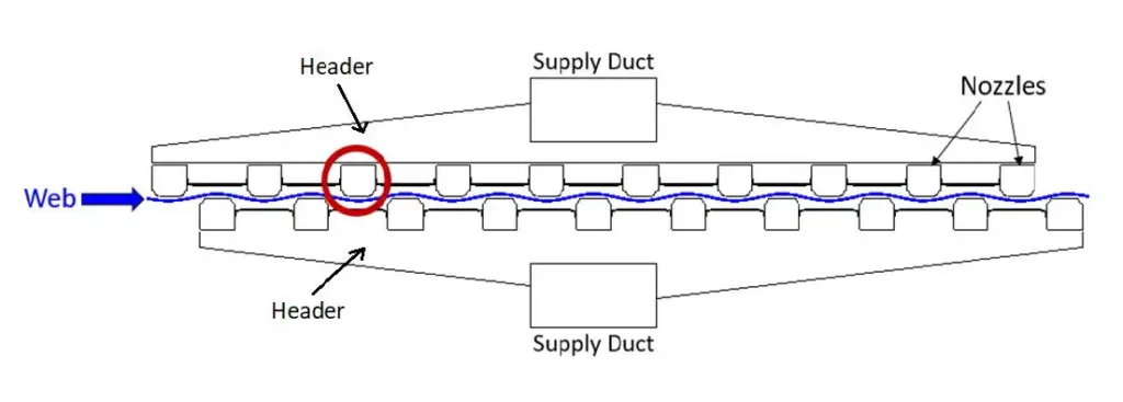
Clean dryer regularly: Uniform drying requires uniform air velocity delivered to the product. Regular cleaning of a drying system will prevent buildup on ductwork, headers and air bars. Dryer supply air is delivered via a supply-air fan through supply ducts, headers and, lastly, through the air bars or nozzles to the product (see Figure 1). A blocked air bar will be unable to deliver equal air velocity to the product across the length of the air bar. Another culprit to uneven air delivery is unbalanced headers. At least yearly, the air flow within a zone’s supply headers should be balanced between top and bottom air (if present) and from side-to-side within each header. This is achieved by adjusting the dampers within the supply ductwork and/or headers, respectively. This typically is a manual adjustment.
Tune burners annually: NFPA 86 requires burners to be inspected annually. Inspection includes testing for leaks and tuning to verify and document the high and low fire positions of the fuel and air actuator(s). An improperly tuned burner either will be running too rich (not enough oxygen) or too lean (too much excess oxygen), and both of these conditions reduce the efficiency of the burner. If the burner is not getting enough oxygen, unburned fuel will be exhausted, soot will form in the system and large amounts of carbon monoxide (CO) will be formed and exhausted to the environment. If a burner has too much oxygen, burner efficiency is reduced as more fuel is required to heat the excess oxygen, the exhaust volume is increased and heat transfer is decreased due to the lower flame temperature and reduced temperature differential.
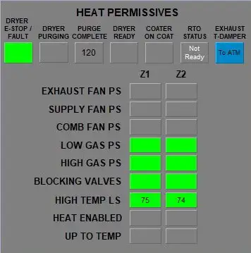
Verify and document the dryer’s safety-chain components and settings: All dryers have a programmed sequence of operation and safety chain that are designed to ensure safe operation of the dryer and to comply with NFPA 86. Figure 2 shows an example of a dryer’s sequence of operation. (More details about Point 4 follow).
Before heat can be enabled, the operation of all system fans, including the exhaust, supply and combustion blowers, must be proven to be operational by pressure switches. At least yearly, each fan’s pressure-switch setting should be verified, documented, and compared with the previous year’s setting. Once the systems’ fans are proven, the dryer enters its purge sequence. NFPA 86 requires four (4) system volumes of fresh air to be introduced and exhausted during the purge cycle to eliminate any volatiles from the dryer. Volatiles can include gas from a burner that is leaking, from the product being dried, or from volatile gases in the environment. The purge timer should be checked, verified and documented annually.
Each dryer zone will have at least one high-temperature limit switch (HTLS) to prevent overheating of the system and damage to the supply fan. Each HTLS should be checked annually to verify operation and that it is set to the proper temperature. Additionally, all actuated dampers on the dryer should be inspected and demonstrated to be operational.
Another important safety component of a drying system is the box negative-pressure transmitter. Dryers typically are designed to operate at a slightly negative box pressure to keep the contents of the dryer inside the dryer and prevent any volatile components from escaping into the plant. The box pressure should be just negative enough to accomplish this. Too high of negative pressure will reduce the efficiency of the dryer as too much ambient air will be pulled into the dryer from the web entrance and exit slots.
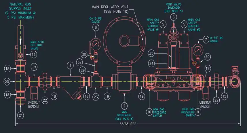
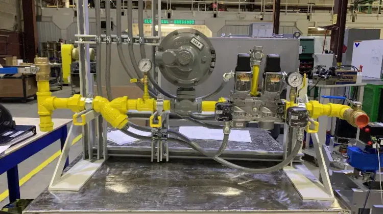
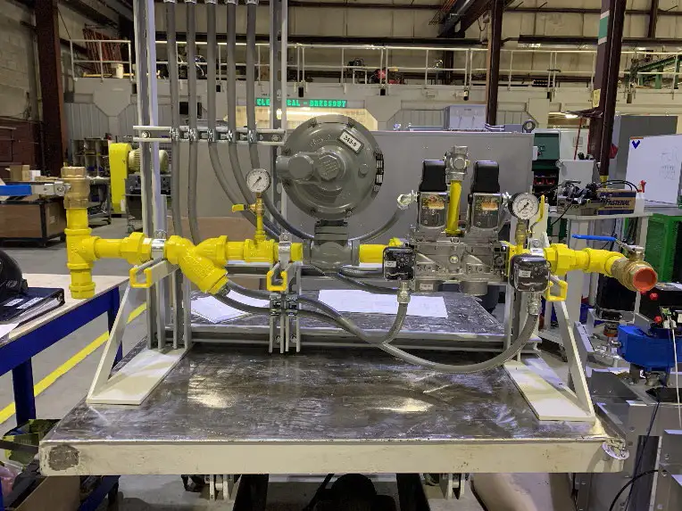
A gas-heated system has many other components that are part of the safety chain. Figures 3 and 4 show a diagram of a pilotless gas train and some of its safety components and an assembled gas train, respectively.
These safety components include a high gas-pressure switch, low gas-pressure switch, ignition timer, flame sensor, safety shut-off valves and a flame safeguard. All work together in the proper sequence to keep a dryer operating safely. A high gas-pressure switch verifies that the gas pressure is not too high to extinguish the flame and a low gas-pressure switch verifies that the gas pressure is not too low to maintain a flame. According to NFPA 86, upon a successful purge, ignition may be initiated for a maximum of 15 seconds on a system with only a main gas line. Upon successful ignition, the flame sensor ensures there is always a flame present. The safety shut-off valves will shut off the gas supply in the event of a fault, such as too high or too low of gas pressure or a flame-out. All of the aforementioned devices are hardwired into the flame safeguard, a controller that continuously monitors the flame and controls the burner to guarantee the burner is operating safely. Lastly, every gas train should be checked for leaks via the “bubble” test at least annually.
If a safety-chain component – such as a fan-pressure switch – fails, the dryer will be non-operational. For this reason, it is recommended to keep spares of the following parts to prevent unplanned shutdowns: a) fan-pressure switches; b) box, supply air, and exhaust-fan pressure transmitters; 3) resistance temperature detectors (RTDs) for supply air and supply fan HTLS; 4) HTLS; and 5) high and low gas-pressure switches, flame rod, flame ignitor and flame safeguard for gas-heated systems.
Web-handling issues: It is common for web-handling issues to show up in the dryer. In nearly every instance, the web-handling issue is caused by a component upstream or downstream of the dryer. Often, a bad idler bearing is the culprit. When facing web-handling issues, all components on the line need to be inspected. A preventive maintenance program should verify the web line and, if necessary, use strings within the dryer to verify no air bars are contacting the strings. The entrance and exit rolls (if present) should be checked that they are at the right height and trammed.
Opportunities to increase dryer efficiency
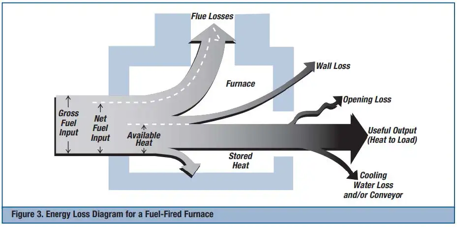
According to the US Department of Energy, approximately 2-15% of total production costs for consumer and industrial goods are for the energy used for process heating (seeUS Department of Energy (2004). “Improving Process Heating System Performance,” p. 3.). Because drying and curing often are the most energy-intensive step in a manufacturing line, there are many opportunities to increase the efficiency of this step by upgrading or replacing the heat-generating equipment, reducing wasted heat to the room and surroundings, and recovering wasted heat. Figure 5 shows a Sankey diagram displaying how the gross fuel input and heat output to the product are affected by such heat losses.
Upgrading or replacing heat-generating equipment: There are several options available for upgrading existing drying and curing equipment to improve efficiency. If your burner is over 20 years old, it is time to start thinking about replacing it as burner efficiencies have improved over this timeframe from about 60-70% to 85-90% today. Over time, the moving parts wear out and are prone to hysteresis which will directly affect the burner’s ability to maintain a good fuel-to-air ratio (FAR) across the entire firing range. A poor FAR results in unburned fuel and large amounts of carbon monoxide exhausted or more fuel being used to heat up excess oxygen. A simple visual test of your burner’s flame will indicate if you have complete combustion. A good natural-gas burner flame will be steady, consistent and blueish/whitish in color. Red and yellow flames indicate the creation of carbon and soot from incomplete combustion.
In addition to hysteresis, burner nozzles and orifices can get plugged and deteriorate over time, and these older burners most likely do not meet current EPA emission regulations. New burners are more efficient, offer better turndown ratios and will be able to maintain a good FAR over the entire firing range.
Other upgrade options include replacing the burner’s actuator and upgrading burner controls to a parallel positioning system. Note that updating the controls on an old burner most likely will not fix the underlying issues. Today’s actuators offer many more steps of control compared to actuators from 20 years ago. More control steps prevent over- and under-shooting the setpoint, better performance, repeatability and, ultimately, less fuel used.
A traditional mechanically linked burner-control system uses one actuator that controls the fuel and air simultaneously and only the high and low fire positions can be accurately set. A parallel positioning system has separate fuel and air actuators that are independently controlled rather than through a mechanical linkage. At commissioning, FAR curves of 20 or more points are created and saved in the parallel positioning controller. These systems offer repeatable, accurate FAR setpoints that are accurate to within 0.10 of 1° and ensure that excess oxygen is kept to a minimum to increase burner efficiency and lower fuel consumption. It is estimated that upgrading to a parallel positioning system will reduce gas usage by 5-25% (see US DOE, “Improving Process Heating System Performance,” p. 17).
Converting existing burners to low NOx burners is another available option to reduce greenhouse-gas NOx emissions. It is estimated that low NOx burners can reduce NOx emissions by 40-85% (see US Environmental Protection Agency. “Natural Gas Combustion.” (1998). § 1.4.4.
Reducing wasted heat to the room and surroundings: Heat lost to the surroundings through the dryer’s outer walls or web slots must be replaced by an equal amount taken from the heat source. To keep dryers operating as efficiently as possible, dryers should be routinely inspected for holes in the cladding; worn-out gaskets around doors, vent-relief panels, and split-hood retraction systems; and signs of insulation degradation where skin temperature reaches over 140° F.
Holes should be patched and worn gaskets and degraded insulation should be replaced. The box negative pressure of the dryer boxes should be kept to the least negative pressure to prevent the dryer’s contents from escaping into the room. This will minimize heat lost to cold air infiltration through the web entry and exit slots. Lastly, production scheduling should be reviewed to reduce idle time, turndowns and cycling between heat-up and steady-state as the stored heat must be replaced every time the burner is cycled between hot and cold.
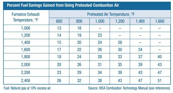
Recovering wasted heat: The first step in any sustainability plan should be to maximize the performance of the existing equipment through regular maintenance and possible equipment and control upgrades. Once accomplished, only then should the option of recovering wasted heat be investigated. Recovering wasted heat can take many forms, including extracting energy from a dryer or regenerative thermal oxidizer (RTO) exhaust stream with an air-to-air heat exchanger. This heat may be used to preheat the combustion or makeup air. Figure 6 shows the percent fuel savings gained from using preheated combustion air with a given exhaust temperature and preheated air temperature. For example, if an exhaust stream with a temperature of 1,000° F is used to preheat the combustion air to 600° F, a fuel savings of 13% can be achieved. It is important to point out that CO2 generation will be reduced by using preheated combustion air, however, the NOx emissions likely will increase due to the increase in the local flame temperature. Alternatively, exhaust air from one zone can be cascaded to another zone to use as preheated supply or makeup air.
Conclusion
There are ample opportunities to improve the performance and efficiency of a drying system. The first step is to get a preventive maintenance and inspection schedule in place. At least annually, the dryer should be visually inspected and cleaned, burners tuned and leak-tested, and safety-chain components verified and documented. A properly maintained dryer can be further improved by burner-control upgrades or burner replacements. Production schedules should be examined for ways to reduce idle time and cycling between hot and cold. Lastly, a heat-recovery system may offer an additional, practical method of increasing the efficiency of your drying system.

Angela Krueger, president of ASI, div. of Thermal Technologies, Inc. (Green Bay, WI), holds a Bachelor’s degree in Chemical Engineering from Northwestern University and a J.D. from The George Washington School of Law. Prior to joining ASI, she was a patent litigation attorney at Fish & Neave and Ropes & Gray in New York City. Angela strives to learn everything she can about a customer’s application to ensure they get a well-designed drying system that will serve their needs for decades. She is a member of the Assn. for Roll-to-Roll Converters (ARC) and the Technical Assn. for the Pulp & Paper Industry (TAPPI), where she serves as the secretary and executive committee member of the Fiberglas Mat Div. Angela can be reached at 920-548-1904, email: alk@asitti.com, www.asitti.com.

