By Neal Michal, principal, Converting Expert LLC
This last installment will present tension dynamics obtained from a representative zero-speed splice event. Recall that the splice takes place while the downstream process runs at full speed. The tension dynamics are repeatable and will be described in phases. A procedure to set up an unwind will be explained. Seven additional references will be offered for further study.
Editor’s Note: Part 1 of this series, “Benefits and challenges of designing and using accumulators in various web-handling operations,” appeared in the 2023 Q2 issue, pages 60-67. It described accumulator design options, challenges and best practices. Part 2, “Using zero-speed splice unwinds in various web-handling operations,” ran in the 2023 Q3 issue, pages 68-75. It discussed the benefits of a zero-speed splice unwind, design options and one method of control.
Tension dynamics
Web tension is the most important parameter for any web process. Individual span tensions will vary significantly within the accumulator during the splice event (see Part 1). It is important to understand minimum and maximum tensions to avoid waste and delay. This often can be done empirically. However, tension sensors, trend charts and videos may be required to optimize difficult processes (see Part 2).

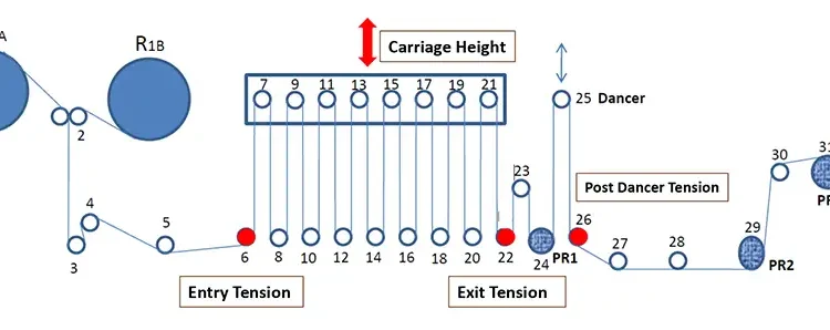
Figure 1 shows the general arrangement of the unwind that was studied [1]. Sensor locations are shown in red.

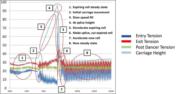
Figure 2 shows the tension dynamics during a splice grouped into eight phases. Analyzing the splice event in phases will facilitate optimization.
- Expiring-roll steady state
- Initial carriage movement
- Slow-speed fill
- At splice height
- Decelerate expiring roll
- Make splice, cut expired roll
- Accelerate new roll
- New steady state
Step 1. Expiring-roll steady state
The total force is distributed across all of the web spans. Note that leading up to the splice event, the exit tension (red) is higher than the entry tension (blue). This is due to the accumulation of bearing and air drag for each consecutive idler in the accumulator. The “post-dancer tension” is set using a single-roller dancer via a similar but smaller air cylinder. For this analysis, this tension can be ignored because it does not vary significantly during the splice event.
Steps 2 & 3. Initial carriage movement & slow-speed fill
The “splice event” begins with the carriage moving from “run height” up to “splice height.” This is achieved by modifying the carriage setpoint height in the PLC. This is referred to as “slow-speed fill.” The initial movement of the carriage is important as this is the first step away from steady-state. Look for any anomalies here. The PI loop may require a softer ramp rate to reduce unwanted tension disturbance. As the carriage rises, the tension differential (exit vs. enter) will increase linear to carriage height. This is caused by the increase in air drag as more material is stored in the accumulator. A small portion of this is caused by bearing drag associated with higher speed to fill the accumulator.
Narrow webs with camber may steer as the carriage moves to splice height. Web steering can change dramatically during the splice sequence. Any web instability during this phase is an early indication that the setup can be improved.
Step 4. At splice height
Splice height is determined by the “Delta fill” (see Part 2). Once the carriage is at splice height, there may be a required delay if a “registered splice” is required. Maximum splice height often is determined by web stability. Web stability will be determined by air drag, speed, web width and web quality.
Step 5. Decelerate expiring roll; pull down
Position loop control is being used in Steps 1-4. The position loop is turned off at the beginning of Step 5. The expiring spindle is commanded to decelerate to a complete stop (see Part 2). During this phase, the spindle is pulling back against the web that is being paid out to the downstream process. It is during this time that the incoming tension will spike. Conversely, the exit tension will drop. Refer to Figure 4 from the Part 2 article on accumulators for additional information. The scan rate for the PLC or the data-collection system will need to be very fast to document the peak load (EG 5-50 ms). Peak load and neckdown at the entrance of the accumulator will vary linear to the deceleration rate.
Step 6. Splice event
The splice bars will close momentarily to attach the new web and cut the expiring web. The time required with the splice bars closed will be an important factor for both Delta fill and accumulator volume for a given web speed (see Part 2). A tape splice is quicker than a heat-seal. Several different techniques are available to reduce this time. Heat-seals may tend to stick to the splice bars if they are still hot when the bars open.
Step 7. Accelerate new roll
After the splice bars open, the new roll is accelerated back to speed. It is a best practice to never allow the carriage to drop below the run height. If it does, all of the rollers will be required to change directions twice (!), resulting in an ugly tension disturbance. If the splice tape is off-center, a narrow web may jump sideways when the new roll is brought up to speed. A floppy edge on a wide web will tend to fold over. A web with a baggy center may “Z-fold” in the middle. Expansion wrinkles near the entrance are common on delicate webs as the tension dramatically drops while the new roll is accelerated up to speed.
Step 8. New steady state
Note the extreme noise. This is because the new roll had a significant flat spot from rough handling. One may need to average the data to sort through the noise. If the downstream process runs in draw control, one may see different tensions after the splice. Typically, this will be a result of roll aging. Some webs will relax over time, others may cinch.
Unwind setup procedure
Prework is as follows. Read and understand the OEM manual. Work with the OEM to find a good starting point. For most processes, wrinkles will be the limiting factor as the process approaches splice height. The following steps are a proven technique to find a good setup. First, determine run height for steady-state operation. Determine the maximum deceleration and acceleration rates that could be used. Select the appropriate rates for the specific web and machine speed. Calculate Delta fill (splice – run height). Make preparations for a process trial while in normal production.
With this knowledge, proceed as follows:
- While at (low) run height, increase tension in the accumulator by ~20% over historical settings.
- Raise the festoon to maximum height (or desired splice height). This step may cause waste downstream.
- Slowly reduce tension until the operator sees instability or wrinkles.
- Bump up tension by a small safety factor.
- Return to run height using the new tension setpoint.
- Update the PLC code and good run settings. Add detailed rung comments in the PLC with the date of change.
- Start trend charts and video recordings rolling. Document 10 consecutive splices to verify the new setup is repeatable. Run both green and aged rolls.
- Review the data collected to look for any unexpected behavior.
- If the carriage drops below run height during the splice, more Delta fill must be added.
- The ideal splice will demonstrate a “soft landing” of the carriage as it switches back to position loop control.
- Update good run settings and limits. Communicate the new standards.
- Conduct quick unwind setup anytime the bill of materials or converting speed has changed.
Unwinding technical resources
There are perhaps over 1,000 peer-reviewed papers describing winding and wound-roll mechanics. There only are a handful of papers that describe unwinds. The following seven resources further describe accumulators, tension dynamics, zero-speed splice unwinds and two computer models.
- “Web Tension in an Accumulator and Industry Needs for the Future,” Neal Michal, 12th International Web Handling Conference (IWEB), June 2009. The data presented in this paper was originally presented in this document.
- “Practical Considerations for Zero Speed Splice Unwinds,” Neal Michal, AIMCAL Applied Web Handling Conference (AWEB), May 2008. This paper describes tension data collected on a narrow-web process with a similar unwind.
- “Dynamics of a Web Accumulator,” John Shelton, 5th International Web Handling Conference (IWEB), June 1999. Dr. John Shelton described the mathematical relationship of span tensions for an accumulator that uses web-driven idlers.
- “Improvement of Control of a Web Accumulator,” John Shelton, 12th International Web Handling Conference (IWEB), June 2009. Dr. John Shelton expanded his 1999 paper by describing the controls required if all rollers were to be driven in the accumulator. This includes the math for an unwind and a winder application.
- “Impact of Web Permeability on High-Speed Web Transport,” Paul Beuther, Neal Michal, 15th International Web Handling Conference (IWEB), June 2015. This paper expands upon the information first presented in 2009. Data are collected from the same process.
- “Analysis of Web Wrinkling in an Accumulator,” Neal Michal, Balaji Kovil-Kandadai, Amol Patel, 13th International Web Handling Conference (IWEB), June 2011. ABAQUS computer modeling of the same accumulator described in 2009. Includes validation work on a pilot line that documents wrinkle behavior versus tram error.
- “Modeling and Computer Simulation of Zero Speed Splice Unwinds,” Prabhakar Pagilla, 16th International Web Handling Conference (IWEB), June 2017. Dr. Prabhakar Pagilla’s development of a Matlab/Simulink computer model for the same accumulator described in 2009.
Items 1, 2, 5 and 6 can be downloaded free at www.convertingexpert.com. Other items can be searched on the Oklahoma State University’s “ShareOK.org” website.
Conclusion
A zero-speed splice unwind can improve productivity by 200% or more. The tension dynamics in the accumulator are the leading cause for wrinkles, neckdown and weave during the splice event. The tension disturbance follows a repeating pattern that can be measured with load cells and documented using trend charts. With this knowledge, one can modify the control sequence to optimize the splice event. Several best practices and techniques have been provided. Additional resources were recommended for further study.

Neal Michal, principal at Converting Expert LLC, has a 36-year career focused on making and converting web products. He was Kimberly-Clark’s senior web-handling expert and led open innovation efforts at the Web Handling Research Center for two decades. Neal was responsible for winding and converting performance. During this time, he led computer modeling efforts for winding, wrinkling, accumulators and tension control. Neal launched Converting Expert to help companies improve capability, productivity and delivered quality. Neal is a technical advisor to the Assn. for Roll-to-Roll Converters (ARC) and launched its Web Handling Committee. He presents training at R2R conferences and is a contributor to Converting Quarterly. Neal can be reached at 770-356-7996, email: neal@convertingexpert.com, www.convertingexpert.com.

