By Takayuki Uozumi, optical engineer, Canon, Inc.
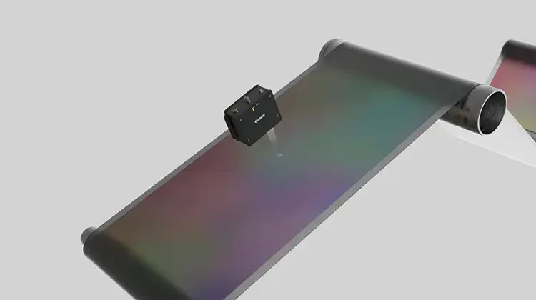
In roll-to-roll (R2R) manufacturing, accurate control of web speed is important for coating & laminating processes, and length management is critical for cutting processes. To measure speed and length, rotary encoders, which rely on physical contact with the surface of the products, are widely used in roll-to-roll manufacturing. Physical contact induces measurement errors attributed by slippage; therefore, non-contact methods are preferable. Although using a laser doppler velocimeter (LDV) is one of few options for non-contact methods, LDV is not very popular due to cost and requirements for its delicate operation. Image-based measurement is another non-contact technique that improves on the weaknesses of LDV. This article will introduce how image-based measurement works and offers some experimental results.
Introduction
In roll-to-roll (R2R) manufacturing, there are quite a few situations where speed control of the material to be conveyed is required. For example, in the coating process, it is required to control the transfer speed to coat the material with uniform thickness. In addition, when two different sheets are laminated, it is necessary to carry them at the same speed. In the cutting step, in which the sheet to be conveyed is cut out at a predetermined length, length control of the material to be conveyed is required.
Conveyance management generally uses a contact-type measuring roll (roller encoder). The roll is pressed against the raw material and the number of rotations of the roll rotating at the same speed as the object is counted by the rotary encoder. In a measuring roll, there are problems such as measurement errors caused by slippage or abrasion of the roll, and scratches on the surface of the raw material by pressing.
Non-contact measurement can solve the problems caused by contact. An LDV (Laser Doppler Velocimeter) is known as a non-contact measurement method. LDV is an interferometer-based technology that is expensive in part because it requires special optical elements. Also, it is known that there is “drop-out” of signal in principle [1]. The response is limited by the time averaging to prevent dropout effects. Therefore, it is susceptible to environmental vibration and cannot follow the high acceleration of the object. LDV is one of the few products available for non-contact measurement, but it is not in widespread use.
Image-based measurement methods have been known for a long time and have the potential to overcome the problems of LDV by applying LEDs and semiconductor processors that are becoming more high-performance and less costly. This paper presents a non-contact measurement method using an image-correlation technique, which is less expensive than LDV and has high acceleration tracking, and experimental results.
Overview of measurement methods
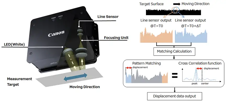
A configuration image diagram of a non-contact measurement method employing image-correlation technology is shown in Figure 1. An image of a surface’s random texture is read by a line sensor, and a displacement is calculated from the correlation of line-sensor outputs acquired in time series. When the cross-correlation function of the line-sensor output acquired at different timings is calculated, the peak position changes according to the displacement. The displacement can be detected with high accuracy by calculating the peak position of the cross-correlation function in sub-pixels. This measuring instrument achieves high accuracy and high sampling rate (4 kHz) by signal processing with original contrivance added to correlation calculation. It has a measurable velocity range of ±10 m/sec and accelerations up to 100 G.
As for the optical system, a telecentric-optical system is adopted, which does not change in magnification even when the distance to the measuring object changes. It is not easily affected by environmental vibration or unevenness of the measuring object surface. A white LED is adopted as the light source. Although it is possible to construct it by laser speckle, it is difficult to suppress the error caused by the curvature of the object [2]. To avoid the influence of the object’s curvature, an incoherent light source is desirable. Hence, the telecentric-optical system is a dark optical system; it needs to be illuminated with a sufficient amount of light, and high-brightness LEDs are employed. Ordinary ambient light is sufficiently small for high-brightness LEDs; the effect of disturbance light is not a problem.
As described above, because the structure is simpler than LDV, a low-cost measuring instrument can be realized.
Introduction to measurement examples
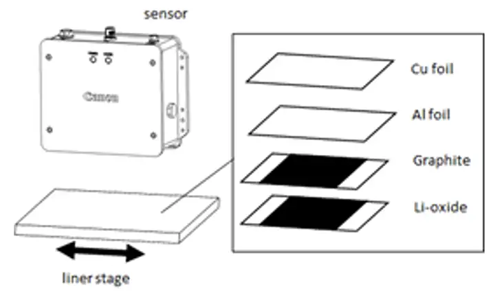
Accuracy evaluation: The experimental environment is shown in Figure 2. An example of measuring a sheet of electrode material (copper foil, aluminum foil, graphite, lithium oxide) as an object is shown.
The measuring instrument shall be installed so as to be perpendicular to the object. Cosine error occurs when the installation-angle deviation occurs with respect to the conveying direction. As it is difficult to adjust the installation angle to zero, calibration is recommended to set the correction factor in the test measurement.
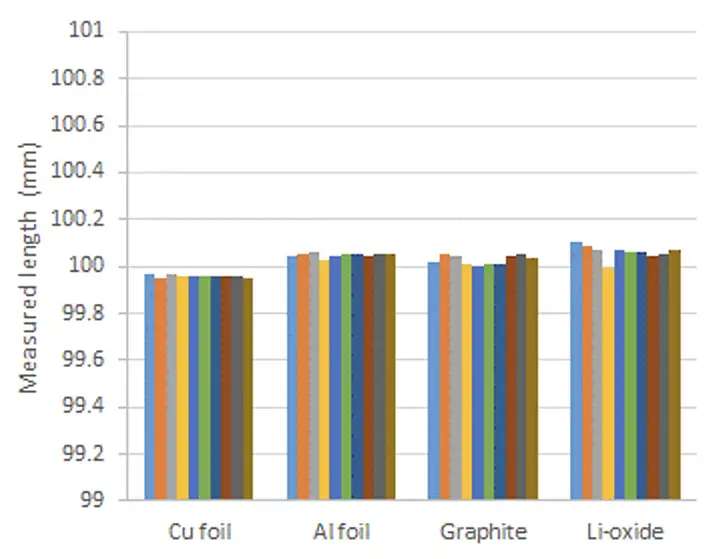
In the present measurement condition, the object was installed on a high-precision linear stage, and it was carried at 100 mm/sec and 100 mm, and the measurement was repeated 10 times.
The measurement results are shown in Figure 3. The error of the mean length was -0.04% to 0.06%. The reproducibility was 0.004% to 0.03% standard deviation. It can be seen that the displacement of the electrode material can be accurately measured.
There are various error factors in the actual process. When the object vibrates or meanders, an error occurs because only the linear component is measured with respect to the actual trajectory. If accuracy is required, appropriate environmental improvement is required.
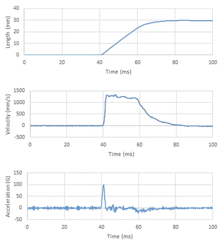
High acceleration tracking evaluation: As an example of following the high acceleration, Figure 4 shows length, velocity and acceleration data when the object is impacted. Even in a situation where acceleration of about 100 G is generated, data can be acquired. Because the data can be obtained at a sampling rate of 4 kHz, the acceleration behavior also can be confirmed. With this measuring instrument, it is possible to observe various high-speed phenomena, although only in one direction.
About the object to be measured
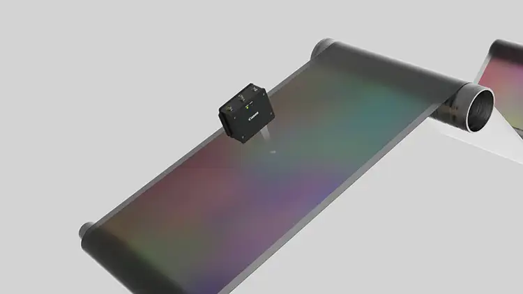
In addition to electrode sheets, there are a wide range of proven measurement objects, including metal materials such as aluminum plates, fibers, paper, rubber materials, building materials, wood and food. A roll-to-roll process example is show in Figure 5.
On the other hand, because surface texture is used as a cue for measurement, it may not be possible to measure the surface texture for objects with poor texture. Unfortunately, the separator has a very smooth surface and stable measurement is difficult. Similarly, measuring transparent films is difficult. However, if there is a pattern, such as printing, on the surface, it can be measured. For example, glossy paper for photography cannot be measured as it is, but it can be measured as long as the image is printed.
Conclusion
Because the image-based measurement method is an inexpensive and robust sensor, the application range of non-contact length measurement can be greatly expanded. It is expected to contribute to productivity improvement as a new measurement tool for solving problems in various production processes.
References
- B. Li, et al. “Study on the measurement of in-plane displacement of solid surfaces by laser Doppler velocimetry,” Optics & Laser Technology. 1995;27;89-93
- T. Inari, et al. “Non-Contact Velocimeter Using Speckle Patterns Produced by Laser,” Transactions of SICE. 1977;13;82-86
Takayuki Uozumi, optical engineer with Canon Inc. (Utunomiya, Japan), holds a Master of Science from the University of Tokyo in 2006. During the past decade, his work has focused upon developing optical sensors. More information is available at http://usa.canon.com/PD.

