
By Dr.-Ing. Jochen G. Koenig, managing director, Schenk Vision
Abstract
While automated optical inspection (AOI) of surfaces such as films/nonwovens/paper and their subsequent converted/laminated products has grown increasingly powerful and versatile, the deployment into day-to-day operations can at times be difficult, particularly as operational and resident engineering staffing are reduced. It has, therefore, been important to focus the development at AOI manufacturers on tools and methods toward the goal of making AOI systems essentially hands-off for day-to-day operation and simplify their initial deployment as much as possible. This is done using various forms of artificial intelligence (AI), which automate tasks such as adjusting light levels, detection levels and defect classification. This article will introduce how these functions generally work and showcase studies of their usage.
Three steps to optimize an AOI system
Once an automated optical inspection (AOI) system has been physically installed and calibrated, it is time to adjust it for the first product(s). Modern AOI usually features multiple views, such as a contrast transmission view and a view that is sensitive to distortions. Multiple views significantly improve not only the detection capabilities but, even more so, the ability to properly differentiate between different types of defects (classification). The cost of this added capability is that all these different views need to be optimized for a product and their classification needs to be developed – using even more defect attributes.
The deployment or dial-in process for a given product to be inspected can be broken into three fundamental steps:
- Adjust light levels and camera gains for each view to optimize the contrast for defect detection.
- Determine reasonable trigger levels (thresholds) for defect capture.
- Develop a classification based on the multiple images the system captured of a defect.
Automatic adaption to material
As our first step, we need to look at setting camera gains and light power levels to get the best contrast in each of the potential multiple views. While this generally is a straightforward task, it can be a bit tricky in some optical configurations.
However, the optimization usually is an iterative process where a procedure can be formulated that operators or maintenance persons can follow. A simple procedure could be as follows:
- Determine the current average brightness in the first view.
- If it is too dark, increase the light power or camera gain; if it is too bright, decrease accordingly.
- Determine the average brightness again. If it is on target, go to Step 1 for the next view; otherwise, go to Step 2.
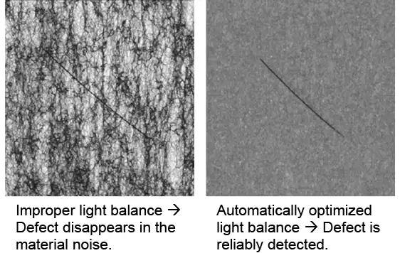
Looks simple enough, doesn’t it? Look at Step 2: Adjust light power or camera gain? The AOI system expert would look at more input, such as overall imaging-system noise or the light source (is it maxed out already?). In some views, particularly in the inspection of nonwovens or otherwise textured materials, there even are multiple lights that need to be properly balanced to achieve optimum imaging. All these additional “ifs-and-whens” quickly will make the task difficult for operators to accomplish during a product change while they are otherwise occupied with changing the machine over to produce the new product.
This is where one of the most classical forms of artificial intelligence can help (see Figure 1). The procedures end up being essentially incremental control algorithms supervised by a simple expert system. The system takes on the role of “expert” in adjusting views by following a set of procedures and making decisions that it has been programmed to do. The AI can do this task so much faster than the human experts and without the risk of making mistakes the humans might run into. As a matter of fact, even this firm’s experienced engineers who are experts in manual adjustments now prefer to use “Automated Adjustment to Material” for its accuracy and speed as everything is settled literally within seconds.
Intelligent detection threshold adjustment
The next step takes us to adjusting the detection of abnormalities to a reasonable level the system can process (see Figure 2). Most all materials exhibit some form of “material noise,” which can best be described as somewhat microscopic variation in the material caused by surface roughness, haziness or patterns in the material, such as embossing. For nonwovens, these even can be rather large area variations, which within certain limits are normal for the material.
The usual strategy for adjusting these thresholds would be to look at the “material noise” and place thresholds at a safe distance. Depending on the process, it is possible that the material noise fluctuates within a product run or from one run of a specific product to the next. In the past, AOI-system vendors sometimes provided a single “sensitivity adjuster” knob. While a convenient quick fix, it happens frequently that, once a system has been de-sensitized with this knob because higher material noise choked the system, it rarely is reverted to its original sensitivity once material with lesser noise is inspected.
What is desired is system intelligence that automatically and continuously determines the best detection sensitivity based on continuously observing the material noise and then adjusting detection thresholds in a fashion that the system’s defect-processing capabilities are best used.
This is accomplished using intelligent noise-level measurement combined with system-load monitoring where the system itself learns where its limits lie. The strategy followed here is basically: “Push the system so that it looks at as many abnormalities as possible without overloading.” Modern main processors with up to 64 processor cores can provide unprecedented image processing and defect-classification power that was unheard of even a few years back.
Artificial intelligence for defect detection and classification purposes (Machine Learning):
Certainly, the most significant impact of AI methods on automated inspection has been made with actual defect segmentation and classification. An abundance of new research has emerged in the field of object recognition in general to segregate objects within an image (or video) and quickly categorize them. Autonomous vehicles come to mind, which need to quickly differentiate what they are “seeing” and track the objects’ movements relative to the car.
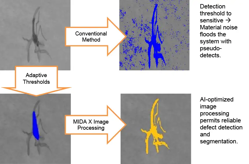
In the image-processing world, the capability to segregate objects within an image is called segmentation. A long used and trusted method in image processing is to first identify an object’s outline by means of simple edge-detection filters that use essentially one or multiple fixed thresholds on image gradients (rate of change). This works well for objects exhibiting a high contrast around their perimeter. When that is not the case and the object gradually fades into the background, these methods will not capture the entire object but possibly just a small, high contrast portion. For example, if we take the insect shown in Figure 2 (top left), we would end up detecting the torso (bottom left) but would miss the legs and wings. The classification would have a hard time identifying that it is indeed an insect.
In the past, it would take experienced image processing engineers and potentially a lot of time to develop appropriate image filtering and segmentation algorithms. Today, AI essentially can take a lot of this tedious work off our hands. This works by simply defining the outline of a number of captured defects in the image as a method to tell the AI system what our desired result of the segmentation would be. The AI then works through the images with literally hundreds or even thousands of different image processing methods and identifies the best suitable one, resulting in advanced image segmentation as observed in Figure 2 (bottom left) – the MIDA X image. On particularly tricky applications, this optimization task may require immense cloud computing power that this firm makes available to its vision-system customers.
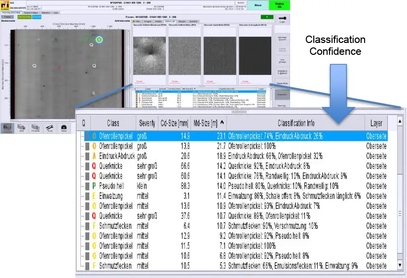
Now that we have segmented defects successfully, the final step is to classify them. Classification means that the inspection system, based on the one or multiple images it took of a defect, determines automatically the defect type. A simple example would be that we want the system to differentiate between particles on the surface from those embedded into the material (i.e., a gel in a plastic film).
The classic way of doing this is for an experienced application engineer with in-depth knowledge of numerical values that describe a detected defect (features) to write rules by hand. On a single image with obviously different appearance, this works well. Once multiple views are used, the task can become very complex and will, in all likelihood, not lead to the best results. For a few decades now, auto-classifiers of different flavors have been implemented in AOI systems to simplify this work. No matter which general machine-learning technology is used, for it to produce a result, all need to be “taught” what we are looking for. What that means for our inspection system is that we need to collect a number of defects, which are imaged by the system and sorted into various categories. Once a system is physically installed, it initially will be set to simply capture everything that is different from the material itself. The user then will review the captured defect and collect similar defects into individual buckets. This process sometimes takes as little as a few hours but highly depends on the actual defect rate and products run.
Three object-recognition algorithms
Once we have a reasonable library of categorized defect images, we now have a good foundation to further improve classification. There are essentially three groups of object recognition algorithms.
A Decision Tree is basically a set of branches in a road where the answer to a True/False question decides on which branch to continue. Finally, the defect would arrive at one of the “leaves” of the decision tree, where each leaf represents a specific defect.
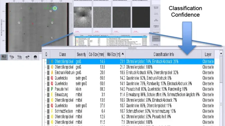
An enhanced version of the above-described binary tree is the so-called C5.0 Algorithm. It basically states for each defect how certain it is of the category into which it would put this defect. For example, it could state that it is calling a defect “a gel” with 70% certainty and “a carbon” with 30% certainty.
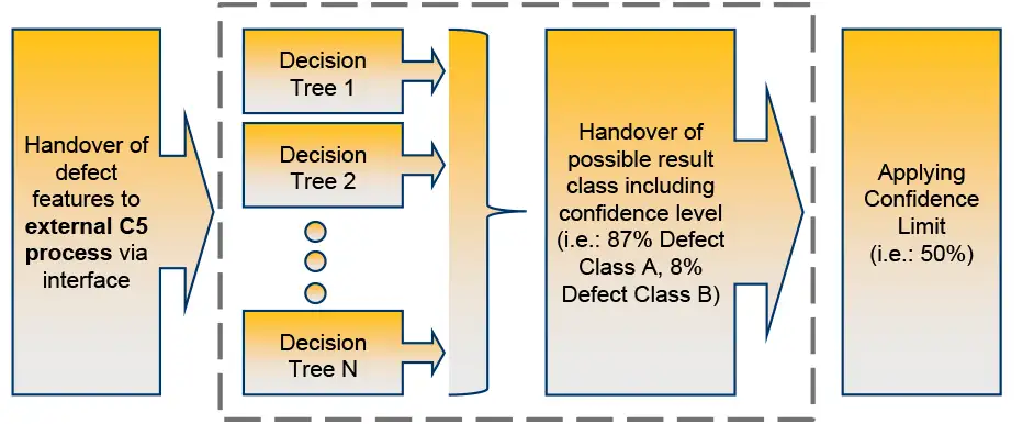
We now have probabilities associated with the decision a particular C5.0 tree delivers and now can apply a technique called boosting (see Figure 3). Because decision trees can deliver somewhat different results based on, for instance, which numerical feature is looked at first, we can have the C5.0 engine create multiple decision trees and then combine their probabilities. This is essentially like having multiple people look at a defect and collect their decisions. As a result, we obtain a combined set of defect-class probabilities and can classify the defect based on which one has the highest probability. However, we also can set a threshold, say 60%, which would provide a defect-class decision only if it is above 60%, and otherwise call it “unspecified.” This permits us to instruct the AI system to provide a result only when there is a clear decision. Call it a “decisive vote.”
One advantage of decision-tree-based auto-classifiers in industrial applications is that they need a comparatively small set of teaching samples. We also may follow the information that leads to a classification decision through the decision trees.
The user then can decide with a single “knob” as to the minimum confidence the classifier needs to have in its decision to actually make the call. Defects where the classifier is not certain enough would be binned into an unknown category for further refinement.
Frequently, there are cases where we already know how to perfectly classify a defect and do not need AI (see Figure 4). A roll impression has a distinct repeat distance, for example. A good AI classification system needs to provide a means to introduce rules like this and either bypass or complement the AI classification.
Neural Networks have been used for machine learning for many decades as well. Between the late 1990s and early 2000s, there had not been much progress on fundamental issues with high dependency on carefully selected sample sets because neural networks become unpredictable when extrapolating outside the sample range. Recently rekindled research, with a key paper on the subject of deep learning in 2012, has vastly improved their suitability in the field of image-based object recognition and has provided significantly better performance in real-world applications. For industrial uses, the fact that the decision-making of a neural network is not transparent makes them difficult to gradually improve other than by further refining the training set. There also is a general consensus that neural networks require a larger training set compared with the C5.0 approach.
Another AI method of object recognition is a Support Vector Machine (SVM), which is mentioned here for completeness only. Teaching methods for SVM are highly complex and do not suit themselves well for non-expert training attempts.
Importance of a Comprehensive Tool Set
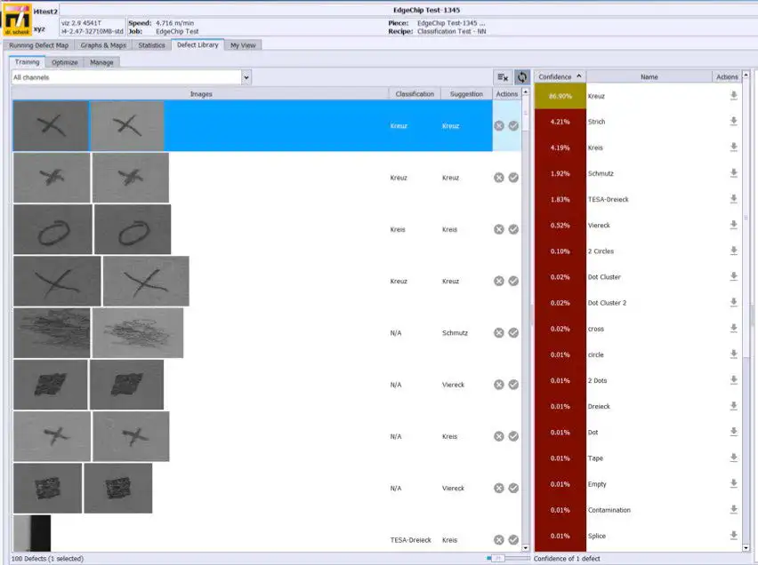
Two key aspects in creating a sample set for machine learning are consistent labeling (what do we want the AI system to call this defect?) and annotation (what is the outline of the defect?).
This firm has recognized the importance of a good toolset to easily facilitate a consistent defect-sample collection. After all, we are teaching the machine here just like a schoolteacher instructs children. If the teachings are inconsistent or conflicting, the results will be just as inconsistent and confused.
We have, therefore, designed a workbench that specifically is geared toward assisting the user in assembling the defect-sample libraries (see Figure 5). For the labeling part, the workbench will, after the user has categorized a few examples of a defect, provide suggestions as to which category a defect may belong. So essentially, the workbench tells the user, “I think this looks like this defect,” and even provides a level of confidence it has in the recommendation.
Achieved improvement of classification
Table 1 shows the improvements made between a single (auto-learned) decision-tree classifier and a boosted C5.0 algorithm.
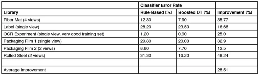
How good a classifier ultimately becomes still depends highly on the quality of the training set, how representative it is of the defects occurring and how many views the system provides to permit differentiation between defects that look alike in a single view.
Summary
Choosing the right artificial intelligence (AI) method for each task when setting up and optimizing an automated optical inspection (AOI) system has significantly reduced the time and effort required (see Figure 6). To use AOI systems to their full potential, users no longer need a person who is an expert in the operation and settings of vision systems. The users now can concentrate on assessing their actual product-quality definition and quickly use the system not only for quality assurance but to identify process issues and correct them. More accurate data provided by the AOI not only ensures shipped quality but also yields significant process improvements and optimizes production output.
Further Reading
Throughout this article, a few key words are in italics. These indicate terms that were used for Internet searches when researching the background for this article.
Dr.-Ing. Jochen G. Koenig, managing director of the Schenk Vision div. of Dr. Schenk of America LLC (Woodbury, MN) studied Electrical Engineering and Automation Technology at the Technical University of Kaiserslautern (Germany), completing his Doctorate at the Institute for Control Systems and Signal Processing. He began working for Dr. Schenk in 1994 with the specific task to build up the US presence of the company. Dr. Schenk of America / Schenk Vision, an AIMCAL, TAPPI, IRMA and AIST member, has just celebrated its 25th anniversary. Schenk Vision is engineering, manufacturing and servicing vision systems for the North American markets. Dr. Koenig has presented at a number of conferences, including the AIMCAL R2R Conferences, AWA, CEMA, SVC and SID. He also is a Faculty Member of the yearly TAPPI Extrusion Coating Course. Dr. Koenig can be reached at 651-730-4090, www.schenkvision.com/us/contact/contactform.html.