
By Carolyn Ellinger, gm-Printed Electronics, Eastman Kodak Co.; and vp-Kodak PE Tech LLC
Print as a manufacturing tool is no longer a new concept, but with so many technologies it can be difficult to understand how to fully realize the advantages that come from using print – particularly in applications where small feature size at high resolution is required. In this article, we will explore concepts that are common across print technologies (such as pixelization, spot size, feature growth and distortion), and how these attributes can vary in practice between non-contact (inkjet) and contact (flexography) toolsets. Information will be presented as “tips” for achieving advantaged, high-resolution, printed-electronics manufacturing.
Editor’s Note: This technical paper is based on a presentation during the Virtual FLEX 2021 Conference in February 2021.
Introduction
Print can bring a variety of advantages to manufacturing, including reduced cost by leveraging additive-patterning technology, and high throughput when implemented in a roll-to-roll (R2R) configuration. While the focus here will be print for additive manufacturing, it can be used to advantage in subtractive processes by reducing the number of required process steps through the direct application of a patterned material, such as an etch resist. In additive processing, there are additional advantages to be realized in novel material-interface control, in-line patterning of multiple materials and novel device architectures – the “Holy Grail” of printed electronics are products with features that are enabled by printing (i.e., difficult to obtain another way) with the cost structure of additive manufacturing.
Whether you are a) an end-application device designer looking for the best-fit of your design to the capabilities of a contract manufacturer, b) a device manufacturer or c) a contract manufacturer yourself looking to promote and align your capabilities to the needs of your customers, it is useful to understand the impact of translating designs into a “printable” design file, and ultimately the desired end-result. The diversity of print technologies and end-use requirements makes it impossible to understand all benefits for a specific product from generalized comparisons. The goal here is to provide thought starters for what questions to ask and how to approach common problems.
Print technologies
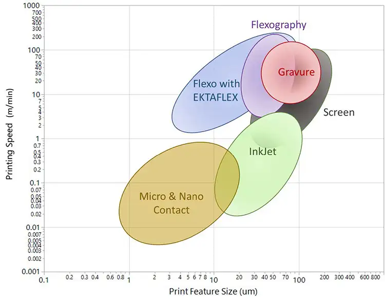
There are multiple articles that compare different print technologies. Figure 1 is a summary of literature data and data obtained from in-house experimentation [1,2]. As shown in Figure 1, there are a range of technologies that offer feature sizes below 100 microns, but only a couple that offer resolutions at 10 microns or below, or at practical throughput levels. In the remainder of the article, we’ll focus on inkjet and flexography.
While both inkjet and flexography can be additive-manufacturing tools, the advantages are not identical. Inkjet is a digital technology, and it allows for variable data for every part within a given production run. There are a variety of inkjet technologies that fall into two broad categories: continuous inkjet and drop-on-demand (DoD) inkjet. The data shown in Figure 1 are representative of drop-on-demand (DoD) technologies, such as piezo, which generate print drops with a shorter flight distance to the media relative to continuous inkjet and often include nozzle redundancy to increase speed. The size of the nozzles in the printhead and frequency of drop generation determine the resolution and obtainable print speed for inkjet systems, which typically are inversely correlated, as shown in Figure 1, meaning that higher resolution inkjet systems have lower print speeds.
In contrast, flexography is an analog, contact-printing technology where the control of the impression of a flexographic plate to the print media controls the transfer of ink to the surface. This contact technology allows for faster print speeds than DoD inkjet technology. Flexographic plates (or sleeves) are patterned with the image to be printed in a prepress operation, which can be an in-house operation or purchased from a prepress service provider. The blue oval in Figure 1 represents data from a high-resolution (12,800 or approximately 2-µm addressability), functional-printing offering from this firm, which can create patterned plates for use in existing flexographic presses.
Understanding “high-resolution” and its benefits
Why does increasing resolution improve the value proposition of using print as a manufacturing tool? Higher resolution means using smaller individual pixels, and smaller pixels mean smaller discrete features or more features in a constrained space. It also means finer incremental control of feature size, which enhances the ability to define curvature and allows for finer control of the placement of features on the page.
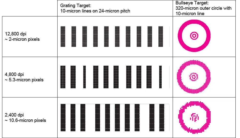
Figure 2 illustrates the impact of higher resolution at the design level. As shown, there is a comparison between three different image resolutions: 12,800-dpi, 4,800-dpi and 2,400-dpi, which have 2.0-, 5.3- and 10.6-micron pixels, respectively. As can be seen, with the 12,800-dpi resolution, a 10-micron line in a 320-micron bullseye target is well resolved with the correct size and shape. As resolution decreases, the ability to control feature size and shape decreases. At 2,400-dpi, even though the pixel is roughly 10-microns, the circularity of the larger 320-micron circle is compromised and the inner 10-micron bullseye is unrecognizable as a circle. In the case of functional prints with traces printed with conductive copper or silver inks, poorly formed shapes will negatively impact conductivity.
The grating targets of Figure 2 illustrate an additional benefit of higher resolution to place features where they need to be within a given design. While a grating target is used for illustrative purposes, it is representative of any target where placement of features is important or critical to the design function. In the 12,800-dpi example, the 10-micron lines on a 24-micron pitch have both uniform spacing and uniform features. As the resolution of the design decreases, you lose control of feature size and placement of features, shown by variability in the gap between features as well as the width of the features themselves.
Although discussions of high-resolution often are centered on minimum achievable feature size (as discussed in relationship to Figure 1, for example), the comparison in Figure 2 highlights the broader benefits of higher resolution to translate arbitrary shapes important in real-world applications.
Think in pixels: Get the most from a tool by optimizing your design to your resolution
Components and devices are defined in real dimensions in a vector design; printed images are pixelated to address the smallest element the device can render. One tip is to consider all designs in pixels; and wherever possible, consider designing in pixels. Looking back at Figure 2, it is possible to make grating-type structures at the lower resolutions by constraining the design to be in whole pixel increments.
The use of single-pixel features in design can pose a challenge in print robustness, so restricting designs to be a two-pixel minimum is a practical limit. For any toolset, establishing and enforcing design rules at the resolution of the toolset will make for a smoother transition from design to printed part. When using multiple tools, understand which tools may limit design and use this information to gain acceptance of incremental dimensions. When using tools having different resolutions, looking for a common denominator in pixel size helps to ensure critical alignments of features can be achieved.
Combine tools to your advantage
All print technologies have pros and cons. By mixing technologies, you may be able to achieve an optimum solution. In fact, in the traditional graphic-arts print industry, it is common to mix digital and analog print tools. For flexible additive manufacturing, a single digital-print station may be all that is needed to enable unique features. Ask yourself, does your design have critical features that are very small and require extremely high resolution? If not, you may be able to use a high-resolution analog solution like flexography for critical features at high speed, and then maintain the speed advantage with variable content from a lower-resolution inkjet tool. Bottom line: Even if your product requires digital print due to a high level of customization by individual unit, digital print may not be required for every layer, feature or material.
Understand spot size and feature growth
Higher resolution has smaller pixel sizes, and smaller pixel sizes enable greater design freedoms. However, feature growth occurs between design and the final print. Feature growth may require you to design “smaller” to accommodate, which may (or may not) require a fundamentally higher-resolution tool. The concept of feature-size growth can be better understood by examining how print technologies (here, inkjet and flexography) transfer the “design-image” to the page.
Inkjet printers generate (roughly spherical) drops of ink which have a drop volume that creates a round dot (or spot) diameter on the page. The size of this dot diameter is controlled by the substrate properties, the ink properties and velocity of the drop when it impacts the page. Given the interactions, achieving a given dot size depends on all the factors of the system. For example, a one-picoliter drop can lead to 20-micron or 6-micron dots on substrate, depending on conditions.
Flexography is a contact print technique where the features on the page are related directly to the features on the plate. The flexographic plate is a relief plate where the ink is transferred from the high spots of the plate to the substrate. The amount of ink transferred to the substrate is controlled primarily by the volume of an anilox roller (a cylinder engraved to deliver a precise and even amount of ink), but the spread of the ink on substrate is tied to ink and substrate properties much like in inkjet printing. Screening can be used on the surface of the features to control the ink volume and spread, but the ink is applied in the desired shape as opposed to building the shape from individual drops that will spread and merge.
Bottom line: There is no universal rule that can be applied to understand the feature growth for every ink-media-print combination. In all cases, whatever is designed as a pixel is going to result in a volume of transferred ink onto the substrate, and while many factors can control the final shape, the printed image will not be exactly what is in the digital design. Placement is in pixels – but feature size is spots on media, requiring optimization of design and establishing design rules to achieve the final feature size. When ink spread and printed spots are considerably larger than the pixel size, shrinking the size of the feature in design by reducing the number of pixels to account for the growth can assist in getting the desired size and shape on the substrate. Again, use of higher-resolution imaging is helpful for fine incremental control of size.
Divide & Conquer: Optimize printing by parsing the image content
Increasing resolution means decreasing the print speed, particularly for inkjet. For single-printhead systems, drop generation frequency limits the print speed that can be obtained. While multiple-printhead designs enable speed increases, there remains an issue of ink drying. For a higher-resolution pattern, inkjet systems may require more ink per unit area due to the spread of the dots and the need to cover the pixel corners.
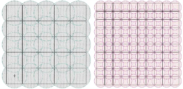
Figure 3 illustrates round spots covering the area of square pixels at low and high resolution. As shown, twice the resolution requires four times the number of drops to cover the pixel area. The reduction in drop volume is predicted to be only around a third for the quadrupling on the number of drops, leading to an overall higher ink load on the substrate, and thus putting greater demands on the drying system.
When resolution is increased in flexography, the print system is tailored to this new smaller feature size. As noted above, the volume of ink that is transferred in a flexographic system is controlled primarily by the anilox. If there are small features on the plate, it is desired that correspondingly small volumes of ink are transferred, and so small features are printed with low-volume anilox and large features with a higher-volume anilox.
For both the inkjet and flexographic examples, superior print quality may be enabled by optimizing processes for different portions of the design. Even when every element in the final product is a single material in a single layer of the device and design, it doesn’t mean the same process conditions are required when printing. Evaluate the elements of the design for features having similar properties, such as size and orientation. If there is a mix of large and small features, most print tools can be configured to have multiple print stations or printheads. For example, different anilox-plate combinations in each station of a flexographic press can optimize print conditions for small and large features, resulting in the desired combined pattern on the final printed substrate. Multiple inkjet heads within an inkjet press can deliver different drop volumes or the design parsed in such a way as to mediate drying issues (for example, printing 50% of the image in two steps, with drying in between).
Reduce distortion impacts with design
Distortion is a common issue in print, particular in R2R systems; in fact, most print systems have some amount of distortion in the printed features. Sometimes this distortion can be corrected in design. Taking the example of flexography, the term dispro is used to describe the correction in the image due to distortion of the flexographic plate when it is mounted on the print cylinder [3,4,5]. A flexographic plate is patterned while flat and then wrapped around a print cylinder. When mounted to a print cylinder, the thickness of the plate causes distortion in the surface features of the plate because the effective diameter at the bottom of the plate is equivalent to the print cylinder, while at the top of the plate (where the printable features are) it is the print-cylinder diameter plus twice the thickness of the plate. This means that the printable surface of the plate has been stretched by the difference in circumference (2*pi*plate thickness) – this known distortion can be removed in the design to remove the effect from the final print. The smaller the cylinder diameter, the larger the correction as the plate thickness is a higher percentage of the circumference / repeat length.
Many sources of distortion are “fixed” due to systematic expansion or contraction of materials in the process, and fixed distortion should be characterized to enable the correction in design and final pattern generation. Variability cannot be corrected in design – designs that are “variability tolerant” is a topic for another day. In all cases, understanding the causes of distortion in a print system and which causes are “fixed” will lead to a more robust process.
Don’t wait to test at scale
It is rare that a research tool will have all the controls of a production system, and research tools typically do not have the ability to operate at production speed. R&D tools are very useful to predict feasibility because it is not practical to do all experimentation at a production scale; however, only production-scale tools can confirm true feasibility and manufacturability. Optimizing on a research tool often is a waste of time. By moving development and commercialization onto production-scale tools, teams can focus on the real problems and to deliver products to customers.
Conclusion
Print can be a powerful electronics additive-manufacturing tool, and there are common considerations across technologies. Better understanding of the advantages and limitations of different print systems leads to creative ways to achieve high-quality products at the lowest cost.
References
- Khan, et al., IEEE SENSORS JOURNAL, vol. 15, no. 6, June (2015)
- Huang & Zhu, Adv. Mater. Technol. 2019, 4, 1800546; Printing Technologies on Flexible Substrates for Printed Electronics http://dx.doi.org/10.5772/intechopen.76161 (2018)
- https://www.teamflexo.com/techtips/formulas-for-plate-distortions/
- http://flexoexchange.com/articles/calc_distortion.html
- Flexo distortion – Prinergy System Administration Guides 8.0 – Kodak Workflow Documentation

Carolyn Ellinger is general mgr.-Printed Electronics at Eastman Kodak Co. and vp-Kodak PE Tech LLC, a subsidiary of Eastman Kodak Co. In her 25+ years at Kodak, she has held technical positions in film systems, flexible displays, nanotechnology and semiconductor devices, MEMS-based devices, spatial ALD and printed electronics. Her research has resulted in peer-reviewed journal articles, multiple contributed and invited presentations, over 70 granted US Patents and numerous improvements to Kodak products. Carolyn can be reached at 585-726-3016, ext. 63016, carolyn.ellinger@kodak.com, www.kodak.com.