By Jerome Flender, Ph.D., solution mgr.-multiphysics simulation, Siemens
Multiphysics simulation of continuous web-handling in converting machines enables engineers to analyze the web-tension behavior of different materials on the kinematic structure of the machine. By avoiding space-intensive prototypes, this approach saves cost, time and wasted-material outputs. This article outlines how “digital twins” replicate the web processing in converting machines so effectively that engineers now are able to use multiphysics-simulation models to optimize machine kinematics, control structures and material handling, leading to increased throughput and product quality. Throughout the machine’s lifecycle, such multiphysics models may be re-employed from virtual commissioning at line startup, to analysis of impact of web-material changes, to condition monitoring of the real machine in production.
Introduction
Developing converting machines is cost- and time-intensive. In the roll-to-roll (R2R) converting industry, the requirements are vast – and continuously increasing. Higher production rates, maximum availability and flexibility, best product quality as well as minimum TCE and TCO costs are demanded.
Converting machines must reconcile these essential requirements for diverse and often delicate web materials. Performance criteria for machines handling diverse web materials are not only quite challenging but also differ. For example, quality requirements for tissue paper are high but clearly different from those of a plastic film for flexible packaging or a metal foil used in a battery cell (anode, separator, cathode).
The waste-free ramp-up of a tissue-converting line running at 600 mpm is one example of a challenge faced by end-users. For the OEM, an example of another challenge might be redesigning a slitter/rewinder originally conceived to produce plastic film rolls for touch screens so that it can produce battery-cell separator rolls instead. This is where digitalization will make the difference by offering shorter time-to-market, higher performance and reduced costs.
Digital twins based on multiphysics models simulating the behavior of the machine running with the web material itself, including automation and actuator models, make it faster and easier to evaluate different mechanical designs, control & regulation strategies, the impact of web-material characteristics, and pre-set optimized drive parameters.
What are those digital twins anyway?
The goal of using a digital twin is to provide a precise digital replication of the machine, enabling system engineers to analyze and optimize the kinematic structure, system dynamics or production efficiency of the machine. This comprehensive definition often leads to the common misconception that the digital twin is “misunderstood as a twin which is suitable for all kind of tasks” [1]. Consistent with the multidimensional-machine functionality and its operating principles, digital twins follow a modular approach by replicating specific machine aspects through individual models. Each of these models are developed in dedicated modeling environments, commonly referred to as simulation tools.
Simulation engineers can choose from a wide set of tools for simulating the focused machine behavior; for instance, using highly specialized-tools respective models such as FEM Analysis, Particle and Thermal Flow with CFD Simulations, Logistics and Plant OEE or Kinematic Motion Solvers, to analyze very specific behavioral aspects of the machine structure or the production process.
Another approach is developing modular models of machine components (partial models), such as drive models, automation and control emulation, or kinematic machine models. By combining and co-simulating these different physical domains, the resulting model replicates the mechatronic-operating principle of the machine and, therefore, is considered to be a multiphysics simulation, which will be the focus in the following.
Figure 1 shows the simulation of a hydraulic press. The real machine (right side of Figure 1) works using a linked chain of different physical domains: the electric drive (orange), the hydraulic circuit (blue) and the mechanical structure (green) operated by activation sequences and control structures in the machine controller (red).
When modeling such multidomain scenarios with multiphysics simulation tools, the simulation engineer uses predefined components from a wide library range, covering mechanics, electrics, signal & control, pneumatics, thermal and many more.
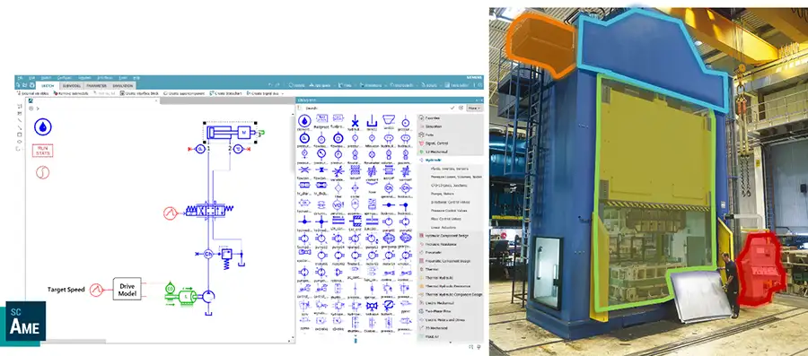
Figure 1 (left) shows the model implementation of this chain, starting with the control structure on the far left, passing on a target speed to a drive model containing a speed controller. The integrated motor model creates a torque which accelerates the pump inertia creating a hydraulic throughput, depending on the pump’s efficiency. The pressure created on the hydraulic cylinder will result in a mechanical-position translation, which is fed back to the superior position control.
Each component model contains an individual differential equation, parameterizable according to its physical domain (PID gains, oil viscosity, inertia, etc.). All components are linked by energy transformations (e.g., rotational speed/torque creating hydraulic throughput/pressure), forming a complex mathematical model that is resolved with numerical solvers. Thus, all system-state variables are accessible, in turn enabling full system transparency.
How do they help me solve my engineering problems?
Multiphysics models open a wide range of virtual-validation scenarios for production machines such as converting machines.
In machine design, engineers may apply different control strategies, vary motor dimensions or test different kinematic configurations to analyze various system structures. Pre-commissioning drive controllers, validating the impact of material or media changes, optimizing activation sequences and reducing oscillations in production processes are some of the numerous ways to increase productivity and secure product quality with multiphysics models. Furthermore, a virtual simulation of a machine avoids the need to set up real prototypes and produce real waste throughout the testing process, saving money and making the engineering process more efficient.
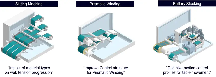
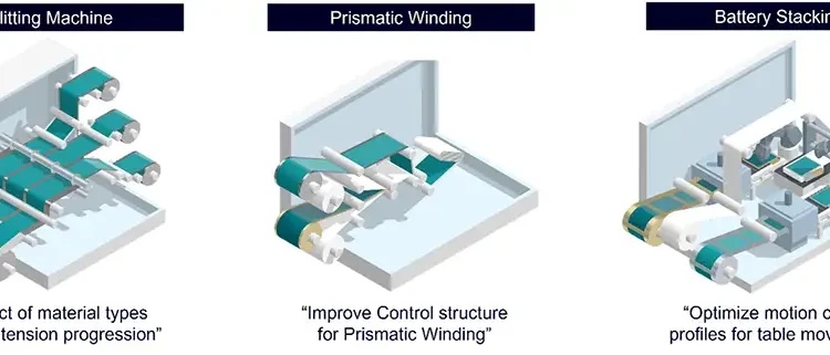
A typical challenge when engineering converting machines is a change in web-tension behavior when switching to another material on a slitter/rewinder (see Figure 2). The different stiffness, elasticity and friction of the web directly affect the mechatronic-system characteristics, resulting in different tension oscillations among web-guiding components. Further, in prismatic winding, the non-round winder shape causes an irregularity in web velocity and tension, which typically is compensated for through web buffer or dancer elements. But which dancer configuration suits the specific machine design best? Which roller weights fulfill the dynamic requirements for suppressing disturbance oscillations, and in which angle should the dancer engage into the web?
How do I create such models, and what do I need for that?
For addressing these challenges, the converting library in this firm’s Simcenter Amesim tool offers a comprehensive set of component templates for modeling web-based production machines, ranging from basic rollers, winders and dancer components to more advanced applications such as lamination, clamping, splicing, position tracking (e.g., for printing presses), non-round roller shapes or web-slipping effects.
The web model itself replicates the lengthening behavior εi of each web segment i based on an algorithm considering the incoming lengthening of the previous segment εi-1, the length change of the segment ai i+1 and the differential velocity vi+1 – vi. With the corresponding Young’s modulus Ei and the cross-sectional area Ai, the web tension Fi in machine direction calculates as Equation 1 [2].

Accordingly, all other component implementations are based on differential equations as well, requiring specific parameterizations, such as roller and shaft diameters, frictions, inertias, etc.
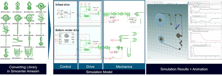
As shown in Figure 3, the model most commonly consists of three parts: the control structure, actuators such as electric drives, and the machine’s mechanics and kinematics. Accomplishing realistic simulations necessarily requires that the model’s structural setup can replicate the ramp-up dynamics and non-linearities (Eigenvalues), as well as the component parameters being precisely defined. Correct parameter identification and the appropriate model approximation typically requires the most time during development of the model.
Show me a practical example
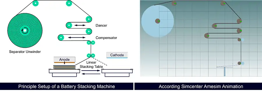
Figure 4 shows a model of battery stacking, where a separator foil is folded Z-wise into layers, in which an anode and cathode are alternately inserted. Precise tension control of the separator layer is crucial for product quality and preventing battery deformation, which may result in dangerous damage.
Starting with the movement principle of the stacking table, different designs are possible (1. rotatory table; 2. moving web over table; 3. moving table), seeking for the one with the least impact on web tension. For this specific machine configuration, results showed that the rotatory table concept had the least impact on the web segment (see top right corner).
Furthermore, adapting the table’s acceleration profile is another possibility to minimize web-tension peaks (see Figure 5). After accelerating fast from the left start position, the web segment shortens when reaching the middle. Decreasing the table speed limits web-tension variations, which are more likely to occur in short web segments. Subsequently, the axis reaccelerates toward the right position, resulting in an “M”-shaped acceleration profile (blue curve). Developing and validating such motion-profile optimizations and the corresponding control structures with virtual prototypes avoid wasting expensive battery materials in test runs.
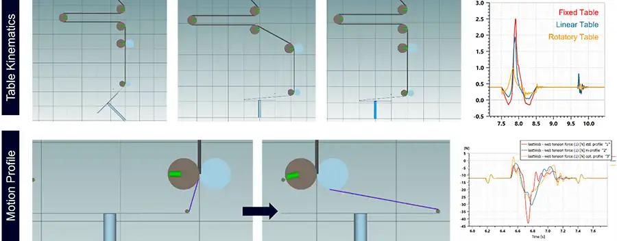
Additional engineering opportunities are optimizing the dancer-roller weights and engagement angle for optimal oscillation compensation, identifying the optimal position of the compensator (closer to the table or closer to the winder) or developing a drive-control concept for the double-roller unit (see “Motion Profile” in), actively infeeding or outfeeding the web in length change.
Can I use these models only in machine engineering?
Aside from the above-described engineering optimizations, additional benefits from the intensively developed model can be achieved if it is reused at later stages of the machine-development lifecycle. The first opportunity is in virtual commissioning.
By connecting multiphysics models with a simulated PLC, the digital twin acts as a physical reference model for testing the automation code. Both models, the machine model including drives, actuators and sensors run in a synchronous co-simulation, executed in the bus cycle time (e.g., 1-4 ms), just like in reality.
Automation engineers thus can validate the original developed user program, technology structures and activation sequences directly on the model, giving physical feedback to the user. This enables detecting errors much earlier in the automation code, interlocks, false parameterization of controllers and wrong automation sequences. Aside from the “normal” input and output values, the model also offers all other physical variables anywhere in the model to the engineer. Providing comprehensive feedback of the dynamic-machine behavior, the model increases system comprehension and even can be used for machine-operator training.
After building the real machine, the operation phase offers further application of the system model for machine operators and producers. Edge devices, which are industrial PCs connected with the machine control, enable model execution in parallel to the machine operation by streaming real target and actual values through the direct ethernet connection (e.g., via OPC UA) from the real PLC into the Edge. The model itself runs as a functional mockup unit (FMU) in a dedicated application (e.g., LiveTwin on Siemens’ Industrial Edge) while its inputs are excited with the same target as the real machine. The identical excitement of the two assets allows a direct comparison of each other’s output values, such as drive torque, web tension, axes speeds, etc. This model-based condition-monitoring toolchain detects deviations between the ideal machine model and the real machine, presuming a high fidelity of the simulation model. Furthermore, the model acts as a virtual sensor providing system transparency of any web speeds and tensions, axes positions or accelerations, motor torques, etc., to the machine operator.
Briefly summarizing
Digital twins enable machine builders as well as end users to simulate, analyze and predict continuous web behavior in combination with the machine mechatronics in a wide range of converting machines.
Using multiphysics models takes machine engineering to another level, not only in machine design but throughout the whole machine lifecycle. Precise physical machine models support machine concepts before building real prototypes, allow material studies without waste outputs, speed up commissioning before Factory Acceptance Tests (FATs) and support condition monitoring of the machine in the real production operation.
The required model structures and machine parameters of such system models certainly scales with the complexity of the industrial machinery and does require modeling expertise, but investing into model-based development will enable faster time-to-market, reduce costs in engineering and operation, and help increase productivity in production.
References
- Boschert, S.; Heinrich, C.; Rosen, R.; “Next Generation Digital Twin.“ Proceedings of TMCE 2018, Las Palmas de Gran Canaria, 2018, pg. 209-218.
- Galle, A.: “Regelungstechnische Untersuchung der Bedruckstoffförderung in Rollendruckmaschinen,“ Chemnitz, 2007.

Jerome Flender, solution mgr.-multiphysics simulation at Siemens (Erlangen, Germany), holds a Ph.D. on Architectural Models of Production Machines from RWTH Aachen University. He works at Siemens with machine builders and production companies to expand model-based development and multiphysics simulation into industrial machinery. Jerome can be reached at +49-162-1797205, email: jerome.flender@siemens.com, https://siemens.com/simulation.

