By David R. Roisum, Ph.D., principal, Finishing Technologies, Inc.
Introduction
Your web’s path may not be where you want it. One remedy is to find and correct the original source of the path upset. This might be as simple as moving the unwinding roll over sideways a bit. More often, it is not quite that easy. Another remedy is to change the path of the web using an active guide. Under ideal conditions, you might achieve hairsbreadth (0.005-in. / 125-micron) accuracies. Those ideals include requiring only modest path-correction rates and distances, clean-cut and straight web edges, as well as good sensors, good guide mechanicals and good controls,
Guiding is one of the oldest of the web-handling sciences. The first Ph.D. thesis, as far as I know, was by the “father of web handling,” Dr. John Shelton, way back in 1968 [1]. His Ph.D. advisor was Dr. Karl Reid, dean of the engineering department and the founder of the Web Handling Research Center. Guiding was the subject of some dozen other theses and 200 other publications. So, why should this history matter to the industry, in general, and you, in particular? It is because most of what you would need to know to design, buy, maintain, operate and troubleshoot a guide already has been laid out by others; all you have to do is either find one of the handful of individuals who knows the subject thoroughly or read about it yourself [2].
Unfortunately, a few builders have not always done their homework [3]. If builders bent a few rules, customers may end up with a guide that can’t correct very far or very fast. If builders broke a rule or two, the guide may be dysfunctional because it destabilizes the web path. However, it also is possible that the customer has unrealistic expectations about what physics allows and current technologies are capable of. So, what do we need to know about this must-know area of web handling?
Sources of path upsets
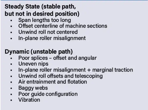
The world is not perfect, and that includes rollers and webs and other factors that can affect web path. Table 1 lists a few of the more common. However, even long before building a machine, it is most important for the designer to shorten web spans, particularly between key processes, such as between the slitting section and the windup [4]. During installation, you want to make absolutely certain that sections share a common centerline. Also prudent during installation is to make sure that every single roller is aligned to something like hairsbreadth tolerances.
Once a machine is running, a path-excursion histogram can be made to pinpoint and quantify the largest sources. This can be done as simply as with a witness line [5] on a roller where path is recorded by a cellphone camera or as fancy as an edge sensor that can be easily moved to audit the entire machine. In any case, it is best to start by identifying your specific path-upset causes and reducing them to the extent practicable before working with guides.
Guide types
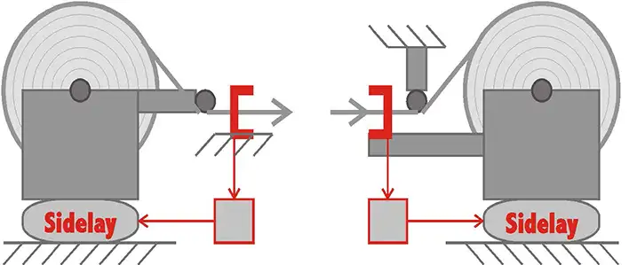
The unwind guide, shown in Figure 1, has the task of getting the web started in a more consistent CD location, despite inconsistencies in unwind-roll positioning as well as roll offsets and telescoping, providing that the correction distance and rate are not too high. Note how the first roller must move with the unwind and that the sensor must be located just before, on or just after that specific roller. This sensor position rule is common to all guides and will improve response times as well as reduce sensor noise due to web-edge curl or flutter.
The winder guide, also shown in Figure 1, has the task of winding more square-edged rolls to improve roll appearance, if not make the rolls more useable. This guide is similar to the unwind except that the roller is stationary, and the sensor is mounted to the windup frame (again, quite close to that key roller). Winder guides are less common because winders are more involved pieces of equipment, so often an intermediate guide is placed just prior to the stationary windup instead.
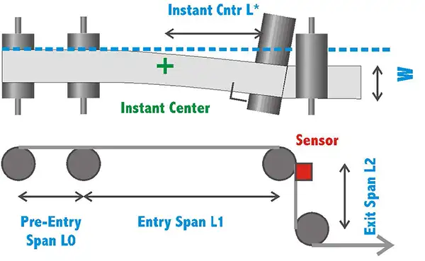
The steering guide, shown in Figure 2, improves web-path position somewhere in the middle of a machine. This might be indicated if the total web path is long. Because the moving roller tilts, in-plane roller misalignment results and because that is the correction mechanism. In-plane bending requires very long spans to avoid diagonal wrinkling or overstressing a web and is thus relegated to only a few special situations, such as found in the metal industry or on long air-floatation ovens in the converting industries. Also required is traction because the web moves sideways to comply with the normal entry law. If traction is lost, the web might not be moved or even move in the opposite direction. Of course, there are many other design requirements that must be considered [2].
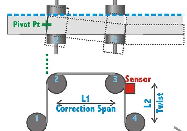
The displacement guide, shown in Figure 3, also improves web-path position somewhere in the middle of a line. However, because this guide does not have in-plane roller misalignment and bending, it does not require as long of spans. Still, there is twisting of the ingoing and outgoing spans so that minimum span lengths must be observed, even if they need not be nearly as long as the steering guide.
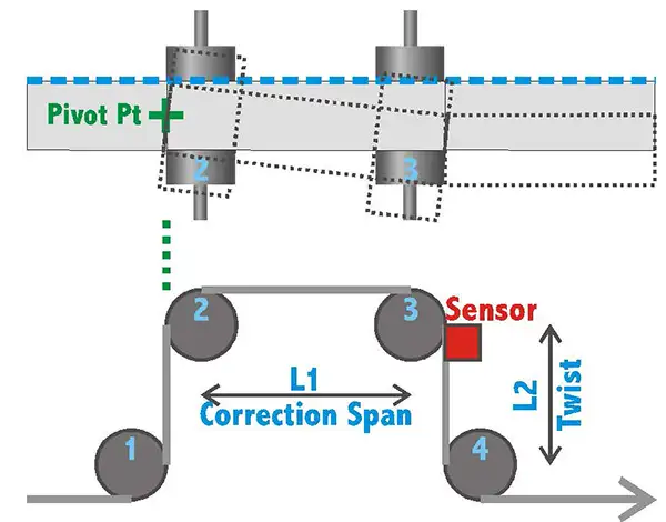
You may find conveyor belts and some industries [3] pivoting a roller from one end, such as seen in Figure 4. Also, wrap angles may not be 90º, as we’ve shown in the previous two intermediate guides. However creative, flexible and inexpensive these designs might be, they will at best always suffer from smaller correction capabilities and slower response. At worst, the guide may wrinkle or overstress the web, not guide at all or even destabilize the position of the web. Those conditions are easy to recognize because the operator will turn the guide off under certain conditions or even permanently.

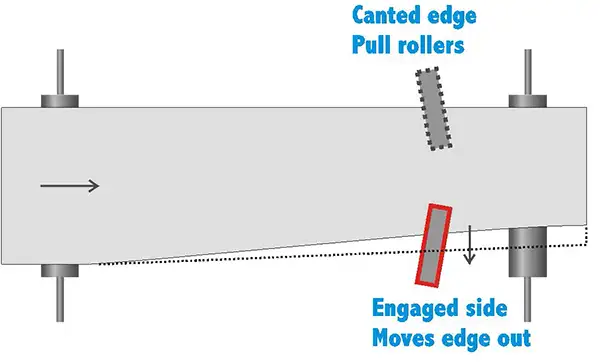
Finally, textiles and few industries use a slack web guider, as shown in Figure 5. These are canted-edge nipped mini-rollers that are turned on and off in a jittery fashion. If one side is engaged, the web is pulled toward that side. If both sides are engaged, the guider becomes a spreader. It also is possible to move the web sideways by moving a roller axially. However, these devices are capable of only tiny corrections, depending on the maximum speed and travel of the roller.
Control architecture
Of course, those are just the mechanicals. We’ve yet to talk about the control architecture that moves the mechanicals. Let’s start with the edge sensor. By far the most common is an infrared light source paired with a detector. The reason is that it is inexpensive (except for wide-array sensors), fast and immune to most disturbances (provided that the sensor is located very near a roller to stabilize the web). However, there are applications where pneumatic, ultrasonic, paddles or cameras are better suited to the task.
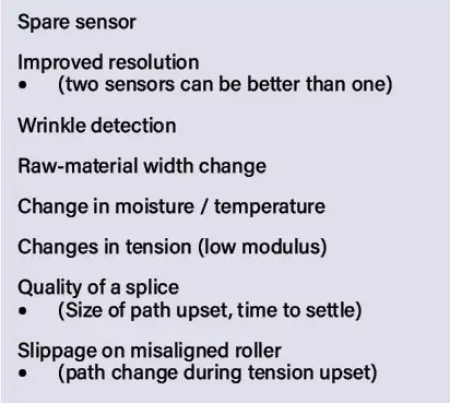
Before we leave sensors, let me stress the absolute importance of (almost) always including dual sensors for the front and back edges for the reasons listed in Table 2. Even if the machine might not currently benefit from two sensors, it might in the future. Even if that machine never would benefit from two sensors, you have the advantage of having only one control box for (nearly) all machines in the plant and even company. That especially is true if that box also is capable of oscillation, which requires the addition of only two sections of control code and no new mechanicals.
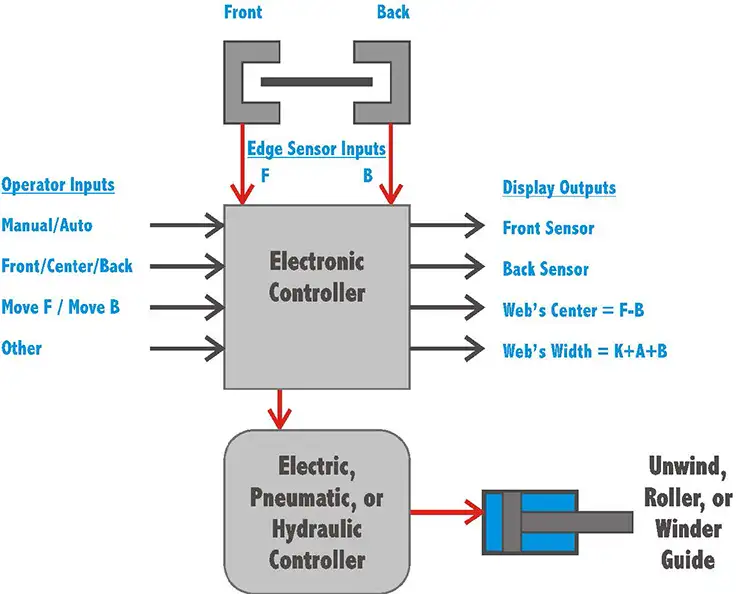
So, when we put all the control elements together, we get something like the schematic shown in Figure 6. Inputs or commands from the operator are on the left and data about web width and position is on the right. The feedback is the (hopefully dual) sensor coming in the top. The part that does the actual work of moving equipment is some type of electric, pneumatic or hydraulic controller, depending mostly on the size (weight) of the equipment needing moving.
The path
There are a lot of moving pieces to make a path-control system perform as good as it can. It starts with understanding the application and what it needs for position accuracy, correction distance and correction rate. Then, we define the source of the path upsets and try to minimize them. Finally, after doing all that, you may wish to add a guide. That part should be the easiest because we’ve studied best practices for a half century, and there are hundreds of documents telling us what those best practices are.
References
- Shelton, John J. Lateral Dynamics of a Moving Web. Ph.D. thesis, Oklahoma State University, 1968.
- Roisum, Walker and Jones. The Web Handling Handbook. Chapter 8, Destech Publishing, 2020.
- Roisum, David R. Insular Industries. YouTube, Web201.73b and c.
- Roisum, David R. DFM – Distances Between Key Processes. YouTube, Web201.48c.
- Roisum, David R. Web Path Movement and the Witness Line. YouTube, Web201.20d.

Dr. David R. Roisum, principal of Finishing Technologies, Inc. (Neenah, WI), is a well-known authority in the field of web-handling and converting. He worked for Beloit Corp. as a designer of winding machinery and later as a research manager, and for Kimberly-Clark as a converting expert. David has accumulated much practical experience working in 1,000+ plants over the course of nearly four decades. He also writes the “Web Wise” Q&A technical column and moderates the Web Handling & Converting Technical Topics Channel for this publication. David can be reached at 920-312-8466, email: drroisum@aol.com, www.roisum.com.

