
By Bruce E. Hyllberg, research specialist, Research & Development Ctr., American Roller Co.
Abstract
Electrically heated rollers have many advantages over hot-oil and hot-water heated rollers. They are very accurate in maintaining a specified temperature, can be changed to a different setting easily and also are extremely uniform end-to-end if the specific technology includes heat pipes. The installation is clean, with no pipes or leaks to be concerned with, and the rollers can be used in virtually any environment (even a vacuum). Routine maintenance is low. This type of roller does not have the same power limitations as hot-oil, and it can be designed for up to at least twice the wattage output and still operate at higher temperatures. All of these factors result in higher lines speeds and lower production waste.
Introduction
The temperature at any point along a heat-roller surface is the result of the heat inputs, the heat outputs and the starting temperature. In a heated roller, of whatever technology, we assume that the heat inputs are uniform end-to-end, but especially within the most important area – the web path. This is not always true, but it’s a pretty good assumption because roller manufacturers work hard to make sure that the heat inputs are uniform along the entire roller face.
Let’s assume that our heated roller produces heat end-to-end in a very uniform manner. The roller is running but has no web on it. The roller surface temperature (300° F, for example) is going to be the same all the way across as long as every area is seeing the same conditions (no air blowing on one end of the roller, for instance). Now we introduce a 5-mil-thick film web with 180° of wrap so that the web is removing a significant amount of heat from the roller. The hypothetical roller is 12 in. in diameter and 60 in. long, but the web is only 40 in. wide.
The temperature of the roller surface in the web path has to drop, at least temporarily, because the heat inputs are the same, but the heat outputs have increased. Depending on the technology of the roller, the temperature will recover quickly and stabilize at a slightly lower temperature, or the operator may have to increase the heat output so that the roller maintains the desired setpoint. Once equilibrium running conditions have been achieved, the heat input to the roller, the roller surface temperature and the temperature of the web as it leaves the roller all will be constant, and the web temperature from edge-to-edge should be fairly uniform.
Outside the area of the roller covered by the web, the heat input conditions are the same, but the heat output conditions are different. There is no web taking heat away. The only heat outputs are some convection losses to the air and some conduction losses to unheated parts of the roller (Note: No unheated parts in an oil-heated roller). As a result, the roller-surface temperature outside the web has to increase to a level higher than inside the web. Not only that, but the temperature will continue to increase until the heat outputs and the heat inputs are equal. Most of this heat loss is typically convection losses to the air.
How the roller deals with this difference in roller surface temperature, inside and outside the web, ultimately will determine the temperature uniformity of the web edge-to-edge. It also will have a significant impact on the production of good product vs. scrap or rework, especially if the web does not cover the full working face of the roller.
Hot-oil roller design and performance
In a basic double-shell, spiral, oil-heated roller, the hot oil flows in one end of the roller and out the other, dropping typically 10° F during transit. The pitch of the spiral oil path changes from end-to-end, changing the velocity of the oil, so that the net heat transfer to the roller shell (outer steel tube) is fairly constant. For the sake of simplicity, let’s assume the oil temperature and the heat transfer to the roller shell are the same, from end-to-end. This actually would be the case if the oil flow rate through the roller was very high.
In the roller example above, we are maintaining the roller surface at about 300° F. In an oil-heated roller, the temperature of the oil has to be higher than 300° F; otherwise, there is no driving force to move the heat to the roller surface. Heat moves only from hot to cold (simplified Second Law of Thermodynamics). The temperature difference between the hot oil and the roller surface is what determines the rate of heat flow to the surface.
Under equilibrium conditions, the oil temperature might be 350° F (at a reasonably high line speed) with the roller surface maintaining 300° F in the web area. Outside the web area, the roller shell is exposed to 350° F internally with only external convection losses to reduce the temperature. The temperature outside the web will rise until the heat inputs equal the heat outputs (heat losses).
The temperature in this area obviously cannot be higher than 350° F, it but may be close to it depending on external heat losses. Let’s estimate a conservative 330° F on the surface. So, outside the web area, the hot-oil side of the roller shell is 350° F in contact with the oil and external surface is 330° F. The average roller-shell temperature is about 340° F. Inside the web area, one side of the roller shell is 350° F, and the outside is 300° F, for an approximate average of 325° F.
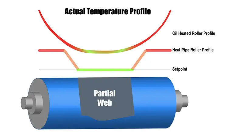
The question is: Will the flowing hot oil remove the excess heat from the roller ends and make the end-to-end temperature uniform? The answer is no (see Figure 1). The hot oil is 350° F, while the average roller-shell temperature outside the web is 340° F. The hot oil will not remove the excess heat – and, worse yet, it will keep adding to it. So, even though the roller has hot oil flowing through it, there is no heat redistribution mechanism to prevent the areas outside the web from overheating. The excess heat outside the web will flow gradually through the roller shell and will produce a curved roller temperature profile rather than a flat one.
This curved profile may adversely affect the web, depending on how severe the profile is and the quality standards of the product being made. The temperature profile of an oil-heated roller is fairly flat if the web covers the whole roller length. As the web gets narrower, the temperature profile becomes increasingly curved.
Electrically heated-roller design
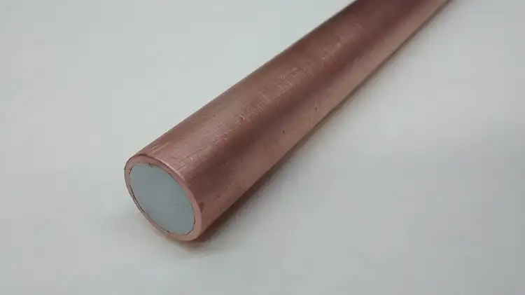
Electrically heated rollers (many but not all) use a passive heat-transfer device called a heat pipe to level the roller-temperature profile under all running conditions. The technology has been around for a long time and is elegant in its simplicity. A heat pipe is an evacuated container containing a media that can exist as both a liquid and a gas in the temperature range in question. Heat pipes can be used over a wide temperature range. For -200° F, the media might be methane, or at +1,000° F, it might be cesium. The container material also has to be non-reactive to the media. For rollers in the range of room temperature to 500° F, the media usually is ultra-purified water, and the container is made of oxygen-free copper. Heat pipes potentially can be used in many types of thermal transfer rollers, even chill rollers, but as a practical matter of cost-effectiveness are used only in electrically heated rollers.
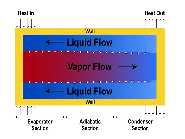
In the heat pipe, there always is equilibrium between the liquid phase and the gas phase (see Figure 2). The only pressure in the heat pipe is from the gas phase. If there is an area that is hotter than the local media, the water will evaporate or boil. The vapor then will move to another location, condense and give up its heat of vaporization.
The vapor moves very quickly inside the heat pipe, hundreds of feet per second, and the detected temperature difference can be very small, even +/-0.01° F. Unlike a solid copper bar, the heat can move from one end of the heat pipe to the other without heating anything in between. So, the heat pipe continuously tries to uniformize its internal surface temperature. Any location that is hotter than the liquid will cause it to evaporate. Any location that is cooler than the vapor will cause it to condense.
The typical commercial heat pipe is a length of centerless ground copper tubing that is sealed at both ends and then evacuated to a high vacuum (see Figure 3). One end usually is sealed with a solder-type material that will melt and vent the media if the heat pipe exceeds the designed temperature range by more than about 50° F. This is a safety feature as the pressure in the water heat pipe is the same as in a saturated steam table – significantly above 500° F. The media then is injected into the heat pipe, which fills about 10% of the internal volume.
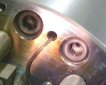
One other component inside the heat pipe is called a wick (see Figure 4). This is something designed to keep a thin layer of water against the inside surface of the tube at all times. With the right wick material, the water can climb the walls of the heat pipe through capillary action even if the heat pipe is stationary. The wick can take many forms: grooves or texture in the internal copper surface, a porous sintered layer of copper powder or a fine wire screen of copper or other materials, to name a few.
In a heated roller, the heat pipe is placed inside a gun-drilled hole that runs the full length of the roller. The hole is only a few mils larger in diameter, and the heat pipe will expand into the hole with use to maximize heat transfer to and from the roller shell. The heat pipe is close to the roller surface but usually spaced more than a quarter of an inch away. There is a bolt circle of evenly spaced heat pipes around the periphery of the roller to provide a uniform surface temperature circumferentially and end-to-end. As long as the maximum operating temperature is not exceeded, commercial heat pipes can perform well for decades. If a heat pipe leaks or fails, it has to be replaced. There is no way to repair it or recharge it. For electrically heated rollers with cartridge-type heaters, there is a second bolt circle of heaters below the heat-pipe circle. There usually are many more heat pipes than heaters.
Heat-pipe roller performance
So, in the roller example previously mentioned, our heated roller is maintaining 300° F on the surface in the web area (see Figure 1). From the point of view of having tight temperature control, the best place for a temperature sensor (thermocouple or RTD) would be close to the heaters, but the actual roller-surface temperature might be slightly lower. From the point of view of process control, the exact roller-surface temperature is what is desired, but this position leads to a lag in temperature control because the sensor does not immediately know when the heater has turned on or off. If we position the sensor below the heat pipes but above the heaters, we should avoid having the control system hunt for the setpoint temperature and still be able to know the surface temperature within a few degrees.
Like the oil-heated roller example, the heaters will have to be hotter than the roller surface so as to deliver heat to the roller surface. Unlike the hot oil in the hot-oil roller, it is unimportant what the heater surface temperature is, nor do we try to control it. The control system will maintain the setpoint temperature based on the location of the sensor in the roller shell, and the heaters will turn on for the percentage of time needed to maintain that setpoint. Under a given set of running conditions, the difference between the roller surface temperature and the temperature at the sensor always will be the same, thus simplifying process repeatability.
The situation outside the web is the same as the oil-heated roller. Heat is produced uniformly along the entire length of the roller, but only a small amount of heat is being taken away outside the web. As a result, the temperature rises until the heat inputs and heat outputs are equal, with one exception. At some point, the heat pipe notices that the internal temperatures inside and outside of the web are different, so the heat pipe starts transporting heat from the roller ends to the web area where the average temperature is lower. This has the effect of making the roller-surface temperature profile outside the web flat (uniform) (see heat-pipe roller profile in Figure 1), but at a different temperature than inside the web.
The difference in these two temperatures has to do with the thermal conductivity of the steel roller shell, the distance the heat pipe is below the roller surface, the average watt density of the roller and the effective thermal resistance of the heat pipe. A typical value might be a uniform 10° F hotter outside the web. In other words, there has to be a difference of 10° F on the roller surface before the heat pipe sees any difference in temperature where it is located below the roller surface. Looking at it another way, it takes a 10° F temperature difference to transport the excess to the heat pipe. At the same time, the temperature inside the web is uniform all the way to the edges but is close to the controller setpoint.
Heat pipes in a thermal-transfer roller always will work to make the temperature uniform in the web area right up to the edges and will take any excess heat and move it to where it can be used. The temperature outside the web also will be uniform but at a somewhat higher temperature. If the web width is changed, it will take the heat pipes only a couple minutes to adjust to the new wider or narrower conditions. After that, the web area will be one uniform temperature, and outside the web will be another uniform temperature.
How uniform is uniform?
Roller manufacturers typically specify a temperature uniformity of +/-1° C (1.8° F) for all types of heated rollers in an idle condition, but most do not specify the temperature variation in a running condition. As a practical matter, it actually is difficult to accurately measure the surface temperature of a running roller without specialized equipment. Heated rollers with heat pipes generally can maintain the same temperature-uniformity standard even with changing conditions of web speed, web width and operating temperature.
Bruce E. Hyllberg, research specialist at the Research & Development Ctr. of American Roller Co. (Union Grove, WI), holds a Bachelor of Science in Chemistry from Wheaton College (IL). He joined American Roller as a chemist in 1979, after more than nine years with Goodyear Tire & Rubber as a rubber chemist. Hyllberg was product mgr. for Electrostatic Assist (ESA) and Gravure Printing Roller products from the time he joined the company until mid-1993. He is regarded as an industry expert in this technology and authored the chapter on ESA Rollers and Technology in a college textbook published by the Gravure Assn. of the Americas. Hyllberg’s current responsibilities include product development and technical support for corona treating and other electrical coatings, electrically heated rollers and all types of thermal spray coatings. He is an active member of ASM International, Thermal Spray Div. and holds 24 US patents on various technologies. Hyllberg can be reached at 262-878-8665, www.americanroller.com.