
By Clarence Klassen, P. Eng., KlassENgineering Inc.
Editor’s Note: This is the second technical article in a two-part series discussing the commissioning of a web-handling line. Part 1: Dry Commissioning discussed the individual drives without the web. Part 2: Wet Commissioning covers final commissioning of the line while running with the web and starting a process such as coating.
Introduction
Drive systems for web handling are among the most complicated of drive systems. The drive system is used to control speed and tension in multiple tension zones and with a number of very different machine sections. The driven machines often are supplied by several manufacturers. Drive performance following commissioning and tuning of the drive system depends heavily on the drive technician, machine builder(s), customer management and customer operators. We expect the drive tech to coordinate personnel safety, ensure machinery is protected, tune the drives, configure communication networks, modify the Operator Interface (HMI), replace failed components, train operators and – finally – tune the tension regulators.
How does the drive technician plan and execute the commissioning of a web-handling line drive system in an effective, timely and cost-efficient manner? A general methodology for commissioning the web-handling drive system is presented. The rationale for drive commissioning, tension/dancer calibration, drive tune-up, dry-line commissioning and wet-commissioning activities will be presented. Emphasis will be given to the unwind and winder drives. Finally, a sequence of tuning the multiple tension-zone regulators will be presented.
Review of Dry Commissioning
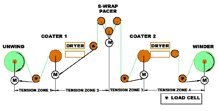
In Part 1, we discussed commissioning of the various drive sections on a web-handling line with multiple tension zones (see Figure 5). All components of the line have been commissioned with a view to running the line as a system. Each drive has been tuned for the same speed-regulator response or for a response required for that section by engineering requirements. Load cells and dancers have been calibrated. Safety interlocks and E-Stops all have been validated as providing the required safety performance. The line has been run to top speed without web. Checks were made to ensure all sections of the line accelerate together.
Particular attention was paid to the unwind and winder drives as these are the most complicated. These drives operate with ever-varying diameter, RPM and torque. These drives may start and stop automatically during roll-transfer sequences.
Wet Commissioning of the entire line with web
Commissioning changes from an individual task to a group activity when the web is introduced. All involved people become interested. For instance, the safety committee arrives with clipboards full of suggestions. Operators will be needed to wrangle the web. All managers, process engineers and equipment vendor reps will be on-site, optimistically hoping for the miracle of the web “on the core and out the door.”
A well-executed startup will give the drive technician the required time to get the web speeds and tensions correct. At the same time, others will be adjusting the coaters. We need a working winder and roll-handling equipment. Cutovers to new rolls must be reliable. People will be needed to supply raw materials and take away scrap.
Establish a quiet zone around your workspace. Nothing is worse than a bunch of people discussing the turkey hunt while you are trying to program a drive controller (at $2,000-$3,000/day). One idea is to tape off an electrical-arc flash zone around the electrical equipment. You are the only person who knows the arc-flash radius, so you can tape off as much space as you need.
Focus on the winder first. In the example, the product comes from an unwind. If possible, use the unwind provided with the line. If your product is extruded, you may choose to set up a simple “A” frame with a bit of braking to support the roll and to be used as an unwind, with material obtained from another source. Simply hold some level of tension at the unwind for now. An operator may need to decrease the unwind tension as the roll depletes.
All middle sections of the line should be run with nips open, if possible, except for the line pacer. Tension regulators for these middle sections will be disabled.
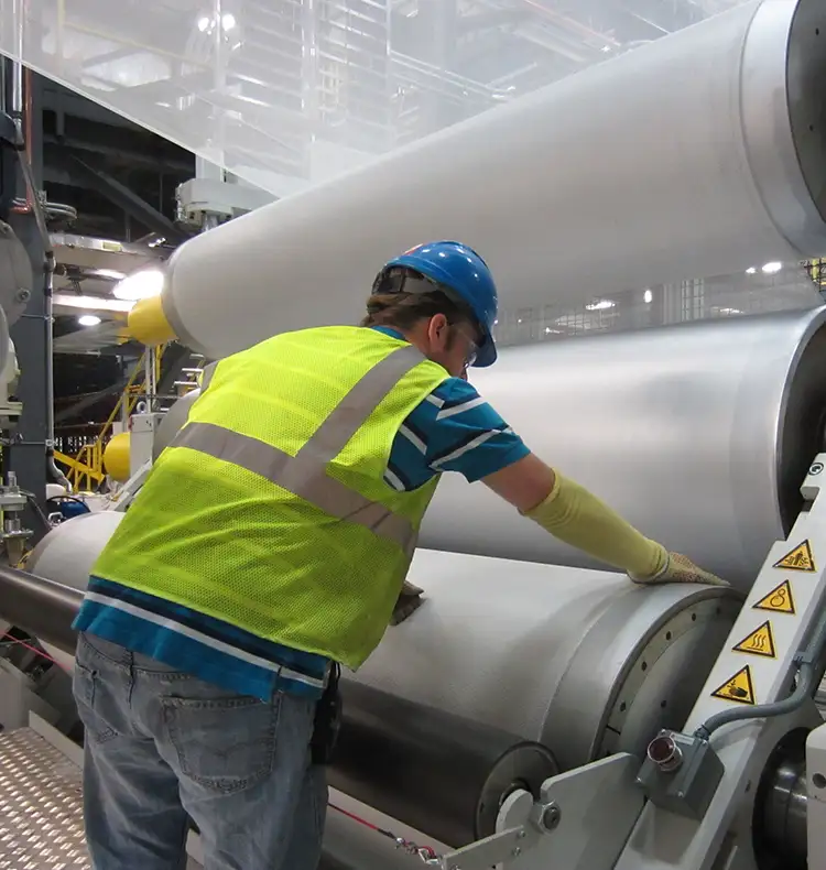
Thread from the unwind to the winder (see Figure 6). This is a chance to develop and perfect threading procedures. Think about SAFETY and watch for unsafe activities.
Wet Run Line Commissioning Checklist: Once the line (or part of the line to the winder) is threaded, the following steps need to be performed:
- Put a core in the windup.
- Put a full roll in the unwind.
- Enable the web-break detectors.
- Disable all tension regulators.
- Disable and preset the actual unwind diameter and winder core diameter.
- Set the unwind and winder tension setpoints to normal PLI (N/m).
- Enable the torque mode for the unwind. The unwind should pull back to establish some tension. Pause work on the unwind for now.
- Enable the torque mode for the winder. The winder should pull forward to establish some tension.
- Run the line at a very low speed (10%). Operators will be needed to stop the line in case of web breaks or roll wraps.
- Monitor the disabled winder-diameter calculator.
- Enable the winder-diameter calculator.
- Enable the winder tension regulator. The tension regulator should modify the winder torque to hold tension to the desired value. It may help at first to reduce the tension regulator authority.
- The winder tension regulator must be tuned. Step the tension setpoint up and then down while running trending software. Trend RPM, tension setpoint, tension actual, tension-regulator output, diameter, torque.
- Increase the winder-tension regulator gain until the regulator starts to oscillate. Then back the gain to 1/3 of the highest value reached.
- Increase the winder-tension regulator integral gain (or integral time constant) until the regulator starts to oscillate. Then back the integral gain to 1/3 of the highest value reached.
- Practice some winder roll cutovers. This may take several attempts.
- Have the winder operator watch the winder tension and roll quality while effort moves to the unwind.
- Monitor the disabled unwind-diameter calculator.
- Enable the unwind-diameter calculator.
- Enable the unwind tension regulator. The tension regulator should modify the unwind torque to hold tension to the desired value. It may help at first to reduce the tension regulator authority.
- The unwind tension regulator must be tuned. Step the tension setpoint up and then down while running trending software. Trend RPM, tension setpoint, tension actual, tension-regulator output, diameter, torque.
- Increase the unwind tension-regulator gain until the regulator starts to oscillate. Then back the gain to 1/3 of the highest value reached.
- Increase the unwind-tension regulator integral gain (or integral time constant) until the regulator starts to oscillate. Then back the integral gain to 1/3 of the highest value reached.
- Practice some unwind splices. This may take several attempts.
- By now the winder diameter is large. Check the tension-regulator stability at a large winder diameter by stepping the tension setpoint. Save the trends.
- By now the unwind diameter is small. Check the unwind tension regulator at a small diameter by stepping the tension setpoint. Save the trends.
- Reduce the authority of the first coater tension regulator to 0% of design speed.
- Set the first coater-tension setpoint to a normal value.
- Establish traction at the first coater, but run it dry. Enable its tension regulator.
- Widen the authority of the first coater-tension regulator to 0.25% of design speed.
- The tension regulator should move the speed in the correct direction to correct the actual tension.
- The first coater-tension regulator must be tuned. Step the tension setpoint up and then down while running trending software. Trend RPM, tension setpoint, tension actual, tension-regulator output, diameter, torque.
- Increase the first coater-tension regulator gain until the regulator starts to oscillate. Then back the gain to 1/3 of the highest value reached.
- Increase the first coater-tension regulator integral gain (or integral time constant) until the regulator starts to oscillate. Then back the integral gain to 1/3 of the highest value reached.
- Increase the authority of the tension regulator to modify speed to the designed value (1 to 2 to 5% of design speed).
- Repeat for the second coater.
- Activate the coaters to apply the coating. Verify that the tension regulators still are stable and that 1% authority to modify speed is enough, even when the coating is applied (disturbance). Save the trends.
- Ramp the line speed to 50%, then 60, 70, 80, 90 and 100%. Save trends of diameters and tensions.
Drive commissioning concludes
You have completed a productive day of wet commissioning with the web. More busy days will follow. Tomorrow, other equipment suppliers will get their chance. Keep the line drives running at their request to permit other equipment – such as extruders, metallizers, laminators, calenders and gauges – to be commissioned.
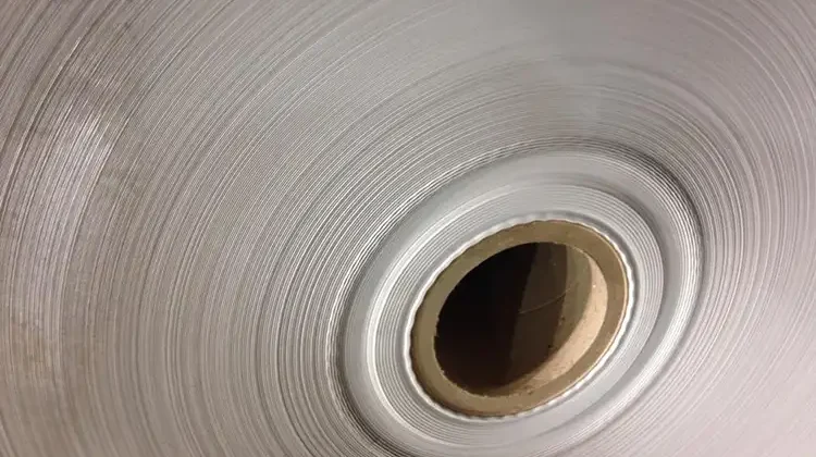
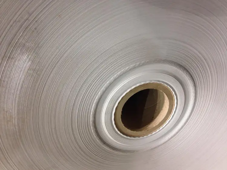
Continue to monitor the drive system. Record all drive faults, diameter-calculation problems and tension-control problems in the log. Improve the quality of the wound rolls (see Figure 7). Wound-roll length can be verified. Cutovers can be optimized. Roll handling can be optimized. Concentrate on keeping the line running so others may do their jobs. Operators, quality-control personnel and managers will be sure to let you know how well you are doing and indicate where improvements are required.
Tension problems can be monitored with the line running by trending the tension-regulator outputs. Spare moments can be used to update drawings and instructions.
Clarence Klassen, P.Eng., principal of KlassENgineering (Peterborough, ON, Canada), is a well-respected drives expert specializing in winders. His background includes a 60/40 split between drive-system design and drive commissioning, primarily with winders and machines for paper and plastic films. His industry experience includes 20 years with employers and more than 15 years of independent consulting. Klassen is an AIMCAL consultant/teacher and member of IEEE and TAPPI. He moderates the “Drives for Web Handling” Technical Topics Channel for this publication’s Website. Klassen can be reached at 800-604-6747, fax: 705-743-2307, email: cklassen@klassen.on.ca, cklassen@ieee.org.