
By Neal Michal, principal, Converting Expert LLC
Abstract
Winders turn flat webs into wound rolls. Increasing line speed reduces total cost to the customer. However, it is common to experience a winder roll bounce at higher speeds – particularly on certain types of webs. Any winder roll bounce can become a serious quality, productivity and/or safety concern. Winder roll bouncing is nearly infamous on high-speed, two-drum winders but also is common on surface winders at lower speeds. A basic model that describes 14 factors will be presented. This model will provide guidance to troubleshoot and address winder roll-bouncing concerns.
Introduction
Winders turn flat webs into wound rolls. Any winding process will exhibit a small amount of vibration. This is inherent due to factors such as poor starts, misalignment, warped cores, etc. Minor vibration does not negatively impact delivered quality or cost to the customer.
Increasing line speed reduces total cost to the customer. However, it is common to experience a winder roll bounce at higher speeds – particularly on certain types of webs. Any winder roll bounce can become a serious quality, productivity and/or safety concern.
Winder roll bouncing is nearly infamous on high-speed two-drum winders. Several papers describe the unusual challenge that two-drum winders present at high speed [1-3]. This has been exaggerated by the commercialization of shaftless, two-drum winders. Bouncing also is common on surface winders at significantly lower speeds.
Critical Speed – Overview
In solid mechanics, the critical speed is the theoretical angular velocity that excites the natural frequency of a rotating object, such as a shaft. All rotating shafts will deflect during rotation. The unbalanced mass causes deflection, which will create a resonant vibration at certain speeds. The magnitude of deflection depends upon several factors. When the rotational speed is equal to the numerical value of the natural vibration, then that speed is referred to as critical speed. [4].
Likewise, a winder roll bounce occurs when the winder excites the building roll or vice-versa. As the speed of rotation approaches the roll’s natural frequency, vibration will increase dramatically.
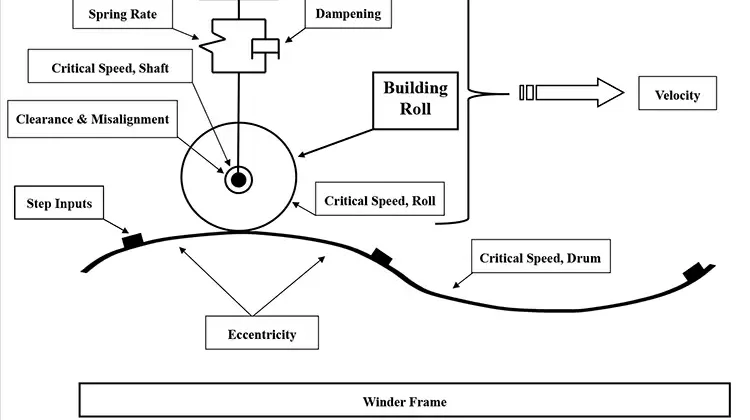
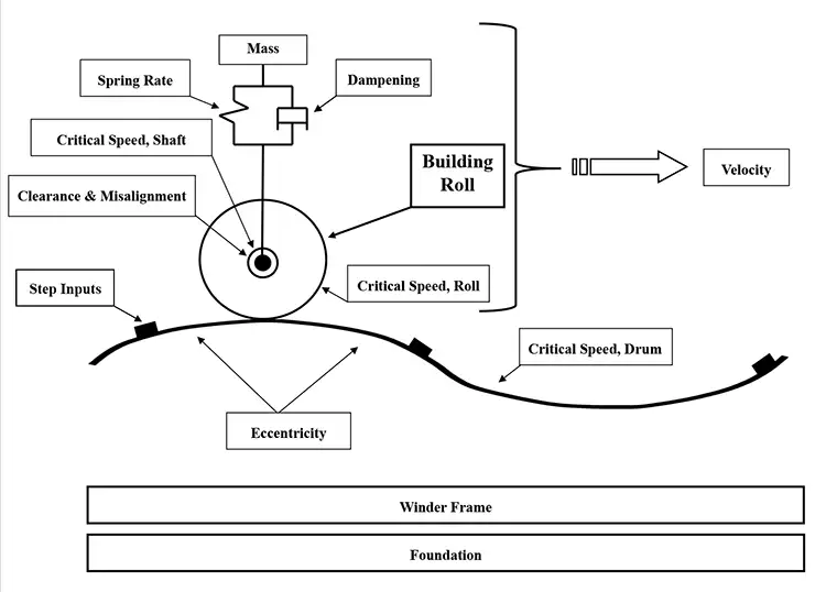
Model: Figure 1 shows a model that highlights 14 factors to consider when evaluating a winder roll bounce. Those factors are as follows:
- Building Roll
- Eccentricity
- Velocity
- Mass, Roll
- Spring Rate
- Dampening
- Step Inputs
- Critical Speed, Shaft
- Critical Speed, Drum(s)
- Critical Speed, Roll
- Clearance
- Misalignment
- Winder Frame
- Foundation
Simplified Model – Overview: A simple model looks at five factors: mass, spring rate, dampening, eccentricity and velocity. Focusing on these five inputs, one can envision the roll acting like a cam follower trying to follow the eccentric path at increasing speeds. Just like a cam follower will “float” at high speed, any winder will bounce rolls if you run it fast enough.
Inputs – Discussion
All 14 inputs shown in Figure 1 will be discussed in this section. The challenge is that most of the inputs are changing simultaneously.
Building Roll: The building roll is the focus of this discussion. The wound roll will build mass with time. The winder inputs (tension, nip and torque [TNT]) will directly impact the wound-roll structure. That structure will directly change the spring rate and indirectly the dampening of the system. Any sudden change in the wound-roll structure may introduce a slip plane where the layers will slide past each other. If they slide in the machine direction, cinching will occur.
Eccentricity: A general sinusoidal curve is shown to represent those items that fall into the eccentric category: rotating shafts, drums, rider rolls, cores, building roll, etc. All rolls will vibrate at their respective natural frequency.
Velocity: The adage “speed kills” certainly applies for roll bouncing. For shafted winders, the natural frequency of the coreshaft often will drive the system’s performance. For shaftless dual-drum winders, the natural frequency of the building roll is more important [2]. Any increase in velocity will magnify the impact of eccentricity, clearance, misalignment and step inputs.
Mass, Roll: Mass will increase linear to time, velocity and basis weight. For most winders, the mass of the material will surpass the mass of the coreshaft. The changing mass will impact the spring rate and possibly dampening.
Spring Rate: The spring rate of the system is a combination of several factors, such as winding roll, wound-roll structure, roll density, stack modulus, core stiffness, core chucks vs. coreshaft and the nip-loading system. For firm rolls, the nip system is the primary factor that determines spring rate.
Dampening: Systemdampening primarily is a function of the original equipment design. Sophisticated high-speed, two-drum winders now offer tuned mass dampers to directly address winder vibration. On the other end of the spectrum, a traditional surface winder may use pneumatic nip loading, which acts as an air spring with little to no inherent dampening. There is a wide array of dampening in between these extremes.
Step Inputs: The step inputs are shown as bumps in the (eccentric) road. One analogy is a gravel road with a washboard surface. Step inputs include things like a poor start at the core, interlayer slippage or damaged winder equipment.
Critical Speed, Shaft: For the same coreshaft (length, diameter, construction), the critical frequency will drop as a function of the cube of the unsupported length. Conversely, it will increase as a function of the square of the nominal body diameter. These are general guidelines. Work with your OEM for exact numbers.
Critical Speed, Drum(s): For high-speed, two-drum winders, the critical speed of the drum is an important factor. Most OEMs will calculate this and will validate it experimentally. Typically, the critical speed of the drum will be quite high. However, the actual performance may have eroded due to worn bearings, damaged/loose journals or an improper repair.
Critical Speed, Roll: Calculating the critical speed of a wound roll can be done – but typically, it is not needed. The wound roll will announce its critical speed when you pass through it. It is important to remember that for high-speed, two-drum winders, the building roll may go through as many as three critical speeds during acceleration, steady-state and deceleration [2]. Any time the building roll has a critical speed that is an even multiple of the drum’s critical speed, a roll bounce is likely.
Clearance: Any mechanical clearance can cause or dramatically increase a roll bounce. There are many opportunities for clearance, such as the following:
- Latch mechanism used to hold a coreshaft
- Loading arms clearance in the machine direction or transverse direction
- Indexing mechanism to move the building roll from one position to the next position
- Worn-out chains, belts, pulleys, keyways, linear bearings…
Winder vibrations are hard on your mechanical equipment and will wear them out quickly and/or break components.
Misalignment: Misalignment over time is common. If the misalignment is in the plane of the web, this will result in shear stress. Shear stress can build up and then suddenly release, forcing a step input. Misalignment perpendicular to the winder drum(s) will cause differential nip-loading from the operator to the drive side. This can cause a roll bounce as well.
Winder Frame: It is common for winders to be tasked to run much faster than the original design speed. In these examples, every component should be evaluated. It is a mistake to think in terms of only vertical support of the primary loads. Vibration can and most likely will take place in all directions.
Foundation: The foundation under the winder may not be stiff enough to withstand a roll vibration. It is common for the entire floor to vibrate in unison with a roll bounce. When the operations manager is bouncing at his desk 25 meters away, the foundation may not be adequate.
Where do I start?
The following 13 basic tasks will help you to analyze winder roll bounce:
- Do your homework on critical thinking and troubleshooting. Use the “Shape Tool” to cull 90% of the potential root causes [5].
- Do your homework on wound-roll structures and how to document them [6].
- Turn the problem into a cost equation. What is the real cost impact to slowing down on the grade(s) to avoid the roll bounce? How many man-hours does this problem merit? Escalate if required.
- Find the OEM manuals. What was the winder designed to do? What was its rated speed?
- Interview the experts. Ask the operators for their help. When did it start? On what grades? What speeds? Trust but verify their input. Are they following good run settings with limits? How wide are the limits?
- Talk to your shift and day maintenance team. Has the winder been damaged? How was it repaired? What has the team observed?
- Talk to your engineers and technicians. Have they worked on it? What is the history of the winder? What concerns or observations do they have? Do they have any correspondence with the OEM they can share?
- Spend quality time watching good running codes. What vibration is okay? Document by grade what speeds cause a roll to bounce. Do they all bounce? Try to characterize the bounce.
- Review the good run settings. Verify they are being followed. How were the good run settings established? Were they validated? How long ago were they established? Are new ones needed?
- Set up trend charts to monitor the winder parameters. Compare trend plots for a good roll vs. a roll that bounces. What is different?
- Spend time to inspect the winder. Look for damaged, worn or loose parts, etc. Ask the maintenance team to manually index the winder. Look for odd movement or signs of misalignment. Are the air lines or cylinders leaking? Check for consistent nip-loading side to side. Inspect the shafts or chucks for damage.
- Set up a video system to watch all the rolls for several consecutive days. Go back to investigate the ones that bounced. Set up a high-speed camera to document a grade that is known to bounce.
- Ask for permission to run a short trial. Modify the inputs to see how the bounce changes.
Think through the inputs in the model
Roll: Document and use roll density when comparing grades. Roll density is a single metric that is highly sensitive to the internal wound-roll structure [6].
Compare the physical attributes of the webs for a smooth-running grade vs. one that tends to bounce. High web-to-web coefficient of friction (COF) of >0.5 is known to cause more bouncing [1]. If a pattern is embossed or calendered, it may increase web-to-web COF. Rolls are more prone to bounce on surface winders that have a traction coating (>200 RA) as compared to a smooth coating (<100 RA) due to higher nip-induced tension.
Velocity: The big knob on the winder for roll bouncing is velocity. It is a best practice to run 25% below a critical speed. Can you run 10% faster than the critical? The bounce should stop. If so, work with your team to ensure the winder will ramp quickly through the critical.
Dampening: Many OEMs neglect dampening. The winder might be running faster than design speed. Can you add dampening to the winder? Can the air flow to the nip-load cylinders be throttled with a restrictor valve? Can a pneumatic nip-load system be replaced with hydraulics?
It is common to see vibration when old school “gibs and ways” are replaced with low-friction linear rails. Can high-preload linear bearings be substituted? More dampening is helpful. It may not change the frequency, but it should reduce the amplitude.
Step Inputs: Evaluate any step inputs. These are especially important. Focus on the inputs that happen once per revolution. The roll is bouncing; start there. Slab down rolls that bounced. Note any eccentricity. Inspect for signs of gross interlayer slippage. Was there an ugly start at the core? Has the tail slipped at the core?
Step inputs can be forced by the winder. If the kitchen rails are damaged, nip-loading will increase and then suddenly release. This can cause a slip plane to form. The roll will accumulate material in the slip plane. This will cause a one-per-revolution spike and often will begin to form an eccentric roll. Other once-per-revolutions include bad bearings or bent journals on the drum, rider roll or coreshafts. Any damaged roll cover can cause an issue.
Eccentricity: Are your cores warped? What can be done to ensure the cores are centered on the coreshaft? Does the coreshaft have enough air pressure to hold the cores concentric? Are you running multiple slits? If so, are all the cores the same diameter? Are the cores being used several times? Do virgin cores bounce? Does your basis weight oscillate in a harmonic fashion that correlates to the roll bounce?
Spring Rate: More system stiffness will help to reduce vibration. Pneumatic nip-loading systems will display a significantly lower spring rate as compared to a hydraulically nip-loaded system. Winders that load long cores using end chucks will have very low system spring rates. Trial heavy-wall/high-modulus cores to mitigate end chucks. Consider durable fiberglass cores for a trial. It is common to see timing belts to stretch under load. Consider replacing them with chain or a cable-drum design.
Is your nip-loading correct? Is it the same on both sides of the winder? Can you reduce nip load? Can you tare out the mass of your coreshaft?
Critical Speed, Shaft: Are you running a coreshaft close to its critical speed? If you are running an aluminum shaft, purchase a steel one for a trial. If you have a steel shaft, increase the diameter or move to a carbon-fiber shaft.
The easiest way to document your shaft’s critical speed is to conduct a “bump test.” You will find that each of your coreshafts will have a different critical speed. This is due to normal wear and tear. If you find one shaft with a noticeably lower critical speed, it may have been dropped or damaged during an unplanned event.
Misalignment: Misalignment can take many forms, such as:
- Misaligned winder, coreshaft, core chucks, rider roll…
- Timing belt jumped one tooth from one side to the opposite side
- Indexing assembly brings the coreshaft skewed to the axis of the winding process
- Broken bolts inside of linear rails and/or bearings
- Building roll skewed to the winder
- Different nip-loading on the drive side vs. the operator side
- Linear cross-deckle basis-weight profile (high to low across the width)
Winder Frame: Is your winder frame shaking? Call an expert to determine vibration mode, frequency and amplitude. Adding mass to the winder frame sometimes can dampen the vibration. Concrete is a far better dampener compared to steel. Typically, there are several things vibrating at different frequencies that need to be addressed sequentially. New winding equipment may be required.
Foundation: Is the winder mounted over a basement? Can structural steel be used to shore it up? How thick is the concrete, and what grade was used? Was the production line built in a warehouse designed for light traffic? Is a new foundation called for, or do you install a new winder on a proper foundation next door?
Conclusion
A winder roll bounce is a serious situation. Be safe. Ensure there is no concern regarding the safety of your team members. Work smart. Pay attention. Never hesitate to ask for help if you have any questions.
References
- “Field Report – Reducing Roll Bouncing,” www.valmet.com/media/articles/up-and-running/reliability/RTReduceRollBounce/
- “Two-drum winder stability analysis,” M. Jorkama and R. Von Hertzen; Pulp & Paper Canada; 108.5, 2007; https://pdfs.semanticscholar.org/f92b/976cf2ef2c1297f27cd1c047a8cdc5327480.pdf
- “Winder Vibration Related to Set Throw-outs,” Jake Zwart and Walter Tarnowski, PAPTAC 2003 – 89th Annual Meeting, www.spectrum-tec.com/PDFs/WinderRollThrowouts.pdf
- Paraphrased from Wikipedia: https://en.wikipedia.org/wiki/Critical_speed
- “Troubleshooting Industrial Problems using Critical Thinking and Good Science,” Neal Michal, AIMCAL R2R Conference USA, Oct. 2018; www.convertingexpert.com
- “Practical Methods to Improve Wound Roll Quality,” Neal Michal, AIMCAL Applied Web Handling Conferences, 2015, 2016; www.convertingexpert.com
Neal Michal, principal at Converting Expert LLC (Cumming, GA), holds a Bachelor of Science in Mechanical Engineering Technology from Purdue University. With a knowledge of web-handling, winding, converting, packaging, automation and process design, he has 31 years of experience with an $18-billion consumer products company with a focus on improving capability, productivity and quality by commercializing technology solutions. Michal led open innovation efforts at the Web Handling Research Center (WHRC) at Oklahoma State University, chaired the WHRC Winding Focus Team for 14 years, and the Industrial Advisory Board for another two. He also led computer modeling efforts for winding, wrinkling, accumulators and tension control. Michal is the author of six proprietary books and has provided training to 1,000+ students. He can be reached at 770-356-7996, email: [email protected], www.convertingexpert.com.