
By Robert Rae, managing dir.-Sales; Ryan Turner, R&D engineer; and Jennifer Heathcote, business development mgr., GEW
Introduction
The Earth’s atmosphere is a delicately balanced mixture of nitrogen (N2), oxygen (O2) and argon (Ar) gases with trace amounts of carbon dioxide (CO2) and neon (Ne). Precise concentrations vary slightly depending on elevation from sea level but generally are 78% nitrogen, 20.9% oxygen and 0.93% argon. To exist and function properly, humans require oxygen concentrations between 19.5 and 23.5%. Anything less causes rapid mental, physical and respiratory impairment. Slightly greater concentrations do not necessarily cause health issues but increase the likelihood of environmental hazards such as fires and explosions.
An important property of oxygen is that it reacts with numerous other elements to facilitate a wide range of both beneficial and detrimental biological, chemical and environmental processes. By contrast, nitrogen and argon do not typically react with other substances and are classified as inert. In terms of human life, oxygen is essential. Without it, we cannot survive. When it comes to free-radical UV curing, however, the presence of oxygen within formulations – and more critically, at the surfaces of formulations – has the potential to adversely affect photopolymerization. This undesirable interference is termed oxygen inhibition.
Oxygen inhibition
Photopolymerization, or UV curing, is a chemical reaction that uses ultraviolet energy to transform specially formulated liquid-like materials that are wet to the touch into solid polymers that are dry to the touch. Photoinitiators (PI) within inks, coatings, adhesives and extrusions absorb UV wavelengths and produce energized free radicals. Free radicals transfer energy by reacting with other free radicals and materials within formulations, such as monomers and oligomers, to create crosslinked polymers. The total reaction occurs within a fraction of a second, producing fully cured materials immediately ready for further processing
or shipping.
Oxygen inhibition occurs when oxygen molecules (O2) disrupt the crosslinking process and cause premature termination of polymer chains. When oxygen is present, its molecules behave like a monomer, react with energized free radicals and sabotage the desired propagation of the reaction. This interference mostly occurs at the surface of the coating where an ample supply of oxygen in the atmosphere weakens free radicals and/or reduces overall concentration.
Formulations sensitive to oxygen inhibition struggle to fully polymerize when cured in open air. This can lead to surface cure issues that exhibit characteristics often described as sticky, tacky or greasy. Surface-cure issues sometimes produce lingering odors due to unreacted raw materials; higher degrees of rub-off or smearing, which results in offsetting and tracking on substrates, parts and machine components; and diminished functional properties in the cured polymers.
Various countermeasures
For mercury-vapor curing applications, the presence of UVC wavelengths often is enough to counter oxygen inhibition. Shorter UVC wavelengths (200 to 285 nm) have greater photonic energy compared to longer UVA wavelengths (315 to 400 nm) and easily are absorbed by free-radical-generating photoinitiators at the formulation surface. As a result, UVC wavelengths emitted from industrially rated UV-curing systems typically generate enough free radicals at the surface to offset those directly lost to oxygen (quenched) or weakened by oxygen (scavenged). Consequently, many UV-curing processes using broadband sources are relatively unaffected by oxygen inhibition.
In situations where curing systems emit insufficient or no UVC output, applications where low coatweights yield large surface areas in comparison to laydown thicknesses or cases where a greater crosslink density is desired, it often is necessary to modify the environment, formulation and/or lamphead output to improve cure. The challenge with low-coatweight applications is that a larger portion of the formulation’s total volume is directly exposed to Earth’s atmosphere, making it easier for oxygen to rob the process of energized free radicals. While counterintuitive, thinner laydowns are more challenging to cure than thicker laydowns, and it has everything to do with oxygen inhibition.
There are various ways to counter oxygen inhibition in UV processes. For example, flooding the surface chemistry with a non-reactive gas such as nitrogen forces air and its 20.9% concentration of oxygen away from the immediate environment. With an optimal inert-gas quantity, the level of oxygen is sufficiently reduced to prevent interference within the crosslinking reaction. Alternatively, increasing viscosity or thickness of a formulation reduces oxygen diffusion and increases free-radical generation within the coating. This can result in the outermost “top” surface being cured from “the bottom up.” In other cases, photoinitiators and other reactive chemistry concentrations – as well as the irradiance and energy density of UV-curing systems – each can be increased to drive the creation of more free radicals. The goal here is to outpace oxygen inhibition. This is not without limit, however, as increasingly greater levels of UV output and PI concentrations ultimately produce diminishing returns and even can inhibit cure.
Curing silicone-release coatings
Historically, silicone-release coatings have been developed using specially designed surface-cure photoinitiators, which rely on short UVC wavelengths emitted from broadband mercury lamps. Silicone-release coatings are among the thinnest laydowns of all UV-curing formulations, with typical coatweights around 0.6 to 1.2 gsm. As a result, these coatings do not generally require deep penetration of UV energy, which is a notable characteristic of longer UVA and UVV wavelengths.
A UV-cured, silicone-release substrate having “high release” properties requires significant energy to pull apart from a mated pressure-sensitive adhesive (PSA) surface. Conversely, “low-release” substrates require minimal energy to separate. Because silicone additives facilitate ease of release, low-release coatings always contain more silicone. While there are situations in which high-release formulations are UV-cured in open air, oxygen inhibition significantly limits the ability to reduce release energy. As a result, most free-radical, silicone-release coatings cannot be successfully cured when directly exposed to Earth’s atmosphere.
To improve crosslinking, drive low-release properties and maintain tighter process control, release coatings routinely are cured in inert environments. While maximum permissible oxygen levels vary by formulation, coatweight and desired cure quality, concentrations in the neighborhood of 50 ppm are typical. For comparison, air at standard atmospheric pressure contains 209,000 ppm of oxygen. This means that a well-engineered inert system that is closely monitored and maintained is an essential element of both the equipment and the process.
Key control factors
Two factors must be correctly controlled to achieve sufficient curing of a silicone-release coating. The first is the concentration of oxygen dissolved within the coating and the concentration of oxygen directly in contact with the coating surface during the time it is irradiated by UV energy. The second is the dosage, or energy density, of UVC output incident upon the release coating as it passes underneath the curing source. On converting lines, the level of atmospheric oxygen-exposed coatings is controlled using an inert chamber while the level of UV dose is controlled by one or more lampheads.
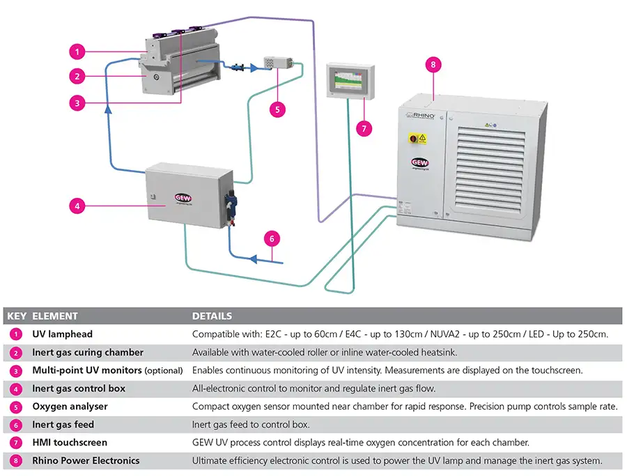
Properly designed UV-curing systems and inert chambers integrate specific controls and sensors to ensure these two factors are under control at the time of installation and throughout the industrial service life of the equipment. Typically, the inert chamber is separated from the UV lamphead assembly by a sealed quartz window. Lampheads are placed external to the chamber and arranged so the energy passes through the window and onto the coated substrate. A typical inert UV-curing system schematic is shown in Figure 1.
Inert-chamber components & operation
An inert chamber first removes the oxygen-rich boundary layer from the substrate and then sustains a low-oxygen environment. Failure to do so may inhibit the formation of free radicals as previously explained.
The boundary layer is detached from the web using angled nozzles vernacularly known as “knives.” There usually is a “knife” at the entrance of the chamber and sometimes at the exit. The nozzle design, orientation angle, distance from substrate and volumetric flowrate of the “knife” are all important variables. The “knife” is prone to contamination by the surrounding environment and must be cleaned periodically. The flowrate, distance from substrate and orientation angle must be adjusted as substrate and process conditions demand. This is because substrate thickness, surface roughness and web speed, among other variables, all have significant impact on the specific equipment setup and settings required to remove the boundary layer.
Sustaining the necessary low-oxygen environment typically is achieved by continuously flooding the chamber with an inert gas, such as nitrogen. For effective silicone-release curing, it is necessary to provide a 99.999% pure nitrogen supply. Constant monitoring and adjustment of oxygen content within the chamber allows for improved process control and a safer production environment. It also helps ensure nitrogen is not wasted.
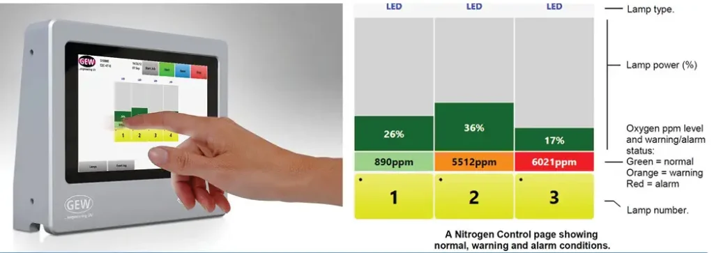
An oxygen sensor is used as a passive measure of oxygen content within the chamber or as part of an interlocked control system (see Figure 2). An interlocked system is integrated with or without closed-loop feedback that automatically adjusts the flowrate of the inert gas to maintain the desired oxygen limit. The oxygen sensor must be kept clean, as with all parts of the chamber, but also requires periodic calibration to ensure accurate measurement. In addition, it is important to remember the position of the sampling tube typically is in the main section of the chamber and not in the boundary layer where inhibiting oxygen still is able to diffuse into the top surface of the coating.
From an engineering perspective, the removal of the boundary layer is easier to achieve if the web is supported around a roller. This allows the entrance and exit apertures and knives to be positioned very close to the web, which minimizes the inert-gas volume needed to maintain a low-oxygen environment. This is increasingly important for today’s wider coating lines.
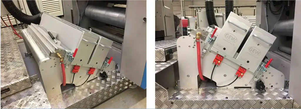
For narrower coating lines, an unsupported web often is passed “straight through” the inert chamber as opposed to around a roller. This typically requires a larger entrance and exit aperture, making removal of the boundary layer more challenging and increasing the required volume of purging gas. Systems with “straight through” web paths often have the advantage of being equipped with a cost-effective hinging mechanism. This provides easy access to the chamber’s quartz window which, due to contamination, requires periodic cleaning. Examples of inert systems mounted around a roller and over a straight-through web path are provided in Figures 3 and 4.
Part 2 of this paper will cover UV-curing systems and best practices for their operation in curing of silicone-release coatings.
Jennifer Heathcote, business development mgr. at GEW, Inc. (North Royalton, OH), holds a Bachelor of Science in Mechanical Engineering from Purdue University and an MBA from the Fisher College of Business at The Ohio State University. She can be reached at 440-381-5606, email: jheathcote@gewuv.com, www.gewuv.com.
Robert Rae, managing dir.-Sales for GEW (EC) Limited, holds a Master of Chemistry from Durham University. Ryan Turner, an R&D engineer for GEW, holds a Master of Engineering in Mechanical Engineering from the University of Exeter. Both are based at the GEW headquarters in Crawley, West Sussex, UK. They can be reached at +44-1737-824-500, sales@gewuv.com.