
By Dave Rumson, slitting educator and consultant
Over the course of my 32-plus years of slitting and winding process observations, educational programs and consultant consultations, I have collected a list of more than 40 winding and slitting tips, tools and pertinent slitting-knife geometric and dynamic setup factors that affect the razor-, crush- and shear-slitting processes. Most you’re probably already aware of, and a few maybe not. Some may help identify and potentially prevent finished-roll defects and/or identify their root causes. I believe that if any one of these tips saves one roll, it can save 100 rolls. My goal is to support your slitting processes. This article will present a few of those tips and tools.
Do’s and Don’ts: Knife storage, knife care and knife shipping
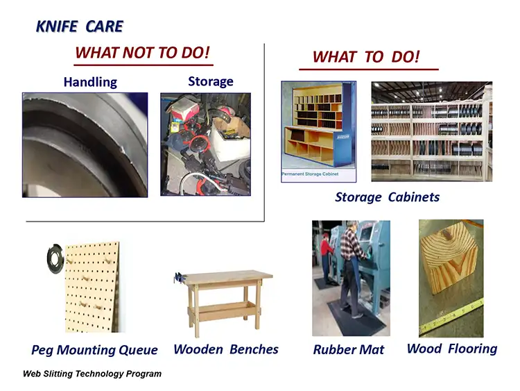
Think of your knives and knifeholders as fine instruments. Be careful with them during non-running activity. Proper knife care pays unseen dividends over time, and there are numerous ways to care for knives. See Figure 1 for some ideas of what to do and what not to do.
These may include storage cabinets and pegboard mounting within a handy location for the next sharpened set to quickly come into play. Consider having wooden benches to work with the knives rather than steel or aluminum benches. Check out rubber floor matting to help protect the knives if accidentally dropped. In my olden days, wood flooring served the same purpose in machine shops.
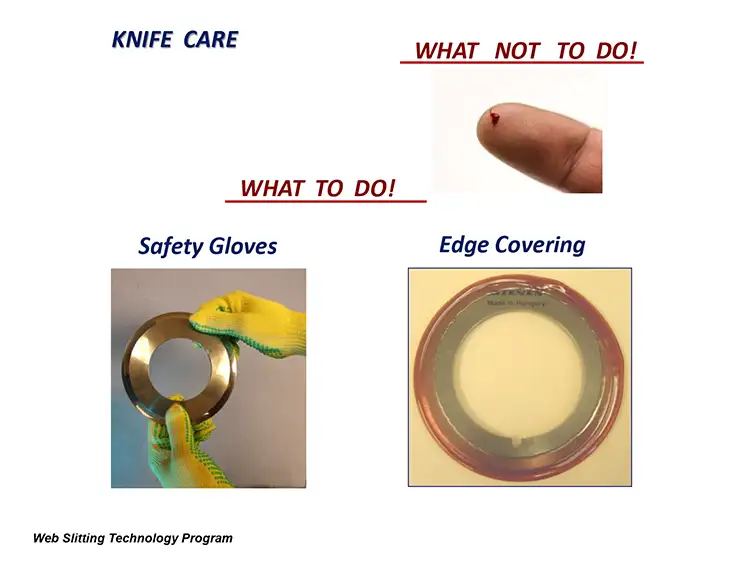
Stay keenly aware of how sharp the knives are (see Figure 2). Don’t cut yourself. Wear safety gloves when handling knives.
Your resharpened knives may come with a rubber or soft edge covering. Warning! While this covering is useful for shipping purposes, an ungloved hand grip on the O.D. easily can push the ultra-sharp edge through the covering. Trust me…I know.
When shipping knives for resharpening, some specific care is needed (see Figure 3). Proper packaging is important. Use containers that hold the knives in place securely for when they’re tossed around during transport.
Don’t package them in cardboard boxes. Figure 3 shows damage made to a tungsten-carbide bottom knife. These knives weren’t totally lost to use, but instead of one resharpening, it took eight resharpenings with that cost and the loss of seven slitting-operation cycles to once again have a useable blade.
Measuring top-knife sharpness
How can we measure Shear Top-Knife Sharpness? There are a number of ways – some good and some not so good. Here are a few.
A very common way is to use a thumbnail. Feel a little resistance and get a little nail dust. This may be good or may not be good enough as judgment is in the hand of the beholder. Either way, it’s dangerous and definitely not recommended.

I knew a knife resharpener who even slid the resharpened blade, on an angle, against the palm of his hand, hoping for a little resistance. I couldn’t believe it, but he did it. DON’T DO THIS.
Don’t wait for the slitting-machine dust levels to build up. This is not so good 99% of the time. So, what’s the 1% slitting-dust measuring system? A process engineer told me that machine Shear-Knife replacement times were based on how much dust was accumulated in the slitting zone after each unwind roll was completed. The company slit very fibrous non-woven materials. After each unwound roll was finished and prior to cleaning, slitting dust was collected from specific areas on the machine and weighed on a gram scale. Once a certain gram weight was reached, the knife changes were made. So, it seems like there’s always a different way to do things. Finally, don’t let customer complaints tell you a knife change is needed.
A better way to measure knife sharpness
What’s a better and safer way to evaluate knife sharpness? Cotton balls and cotton swabs are a great and inexpensive way to check knife sharpness. They will find burrs and snags if the cutting edge is not perfectly sharp. These are a good, fast and simple check if you see some irregularities on finished-roll edges.
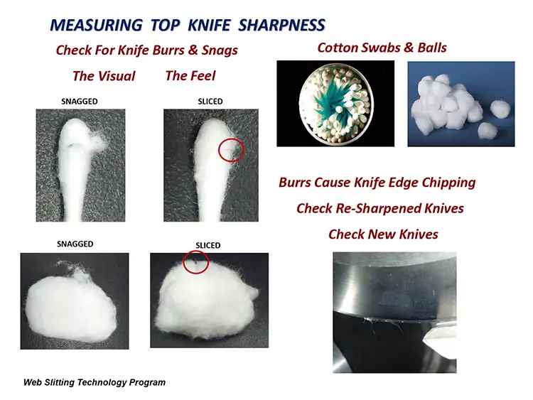
With your safety gloves on, run the swap tip or the cotton ball along the knife circumference. If the knife is not sharp, you easily can see and feel snags on the swab or ball and sometimes on the machine-mounted knife when doing a quick on-line check (with the machine locked down, of course) (see Figure 4).
If the knife is sharp, you’ll see much less snagging and have a clean-looking slice. You also will experience a sense of smoothness along the circumference. You get the feel of it quickly.
Any serious snagging found indicates the potential for that area of the knife’s circumference, if it continues to operate, to chip and fall onto the web, which clearly is a serious quality and regulatory problem for medical and food product rolls.
Lastly, check returned resharpened knives. And while you’re at it, why not check a few newly purchased knives before mounting them on the machine?
Roller alignment
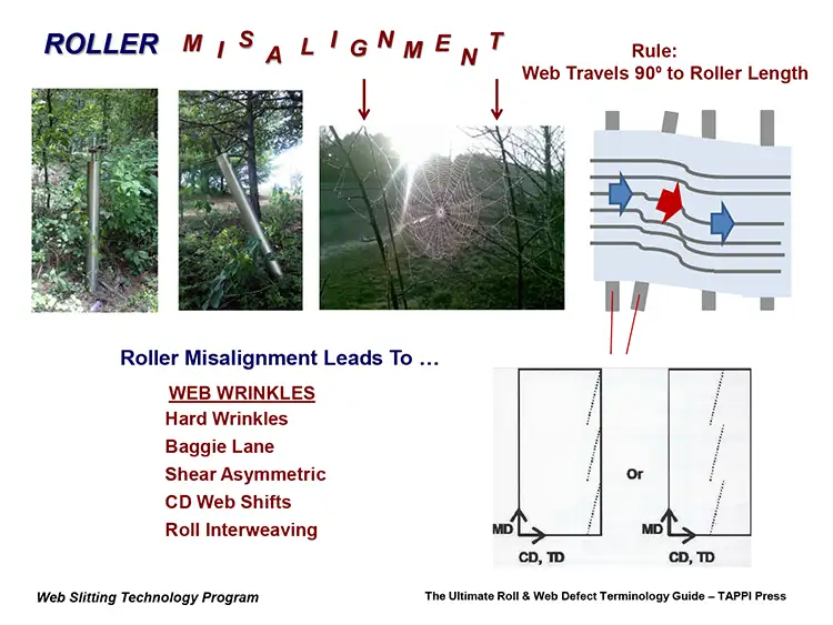
A very important part of the slit roll-making process is having proper alignment of all the rollers in a machine that the web contacts. Years ago, a converting friend invited me to visit his getaway cottage to do some bass fishing on a small pond. After catching the world’s largest Bucket Mouth Bass, I woke up. Later, to unwind a bit, we went for a wooded spider-web-path stroll on his acreage. A short time into it, we came upon an idler roll sticking in the ground. Surprised, I immediately took a photo of it (see Figure 5).
We continued walking, and lo and behold, there was another Idler Roll sticking in the ground. Flabbergasted doesn’t describe my thought process at the time. What I immediately saw was how severely misaligned they were. In the woods, even a spider knows the importance of having the web supports properly aligned.
The first Rule of Thumb of Roller Alignment in a slitter is that a moving web will travel at a 90° angle to the roller length. When two rollers are misaligned, the web will make a cross-machine (CD) shift on the web path, and wrinkles develop. A list of wrinkle types is included in Figure 5.
So, how much misalignment is too much? It depends on the material moving over it. “X” amount to a stretchy web could be bad, but “X” amount to a stiff web might not be so bad. The point is to keep your rollers properly aligned via optical, laser or laser-gyro equipment, especially with older machinery.
Speaking of which, during a client tour of three extrusion lines, wrinkled webs were everywhere. I questioned the date of the last roller alignment. The answer: “I don’t know, but I will check.” Months later, I was told all the lines had severe misalignment. Once they were realigned, there were no more wrinkled rolls. Imagine that.
Slitting-zone in-feed roller misalignment
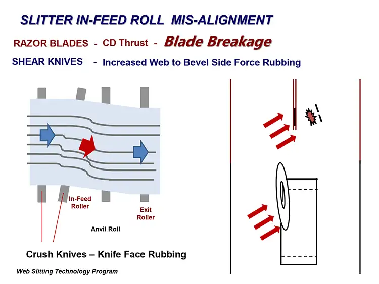
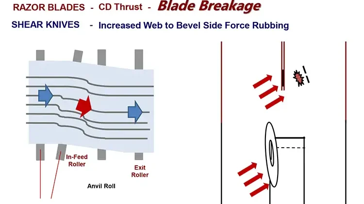
If the Slitting Zone In-Feed Roller is misaligned to the web path, it creates a side-thrusting CD force against the slitting blades or knives. The force amount will vary with the amount of misalignment and the dynamics of winder pull tension and web speed (see Figure 6).
The most serious and not uncommon problem created is when the CD web force contacts a thin razor blade; breakage can happen. Some slitting blades now are as thin as 0.004 in. (0.102 mm), which calls for very tight roll-alignment control.
The Top Shear Knife is mounted on a Shear Angle to the web path to create the all-important Cut Point where the two knives are in friction contact. This knife-setup necessity creates a web-misalignment, dynamic, CD-like force on the web when in knife contact. This may negatively affect finished-roll, slit-edge quality. When the web, if now under an added CD misalignment force, contacts a Top Knife’s beveled face, the level of rubbing and potential slit-edge damage and dusting increases.
A rough Shear Knife surface finish can be a major cutting-edge damage and dust-creating factor, too. Super-finished and/or polished Top Shear Knives with a 1 to 2 RMS surface finish treat the contacting web with much more respect than the standard 8 to 12 RMS smoothness. Rough surface-finished Crush knives, to a lesser degree, also will have increased damage potential although harder to distinguish with all that compressive fracture web damage laying around. Maybe ask your resharpener for the knife’s RMS level. Although RMS and RA are different measure processes, their readings are within 1.1% of each other.
Web-to-roller traction
Web-to-roller traction is extremely important for successful roll making and web slitting. Most winding machinery uses freewheeling idler rolls that rotate under winder pull tension from the moving web. For most web materials, it’s essential that there is no drag to the rotation.
There are two ways to potentially check idler-roll rotation. The first: With the machine totally shut down, use your hands to get a feel of how easy the machine’s non-driven idler rolls rotate and if there are any noticeable rotating-force variations. Rotating “tork” variances must be addressed.
From a slitting perspective, I’ve seen where a rather old Slitting Zone In-Feed Roller was not freewheeling, and staggered force levels were required to rotate it. This could cause a slitting defect that gives the web-cut edge a “sine wave” or cambered-edge defect look. These staggered forces also could exacerbate any Bottom-Knife Axial Run-Out defect issues.
There are certain high-specification machines, though, that have individual, motor-driven idler rolls that can be tuned to handle highly extensible web, ensuring minimum stretch deformation.
The second way to check idler roll rotation: Dab a little machining blue dye to the roll O.D. and run the machine with a section of sacrificial web. If the roller drags and the web slips, the dye will be scuffed. A really good cleaning will be needed as well.
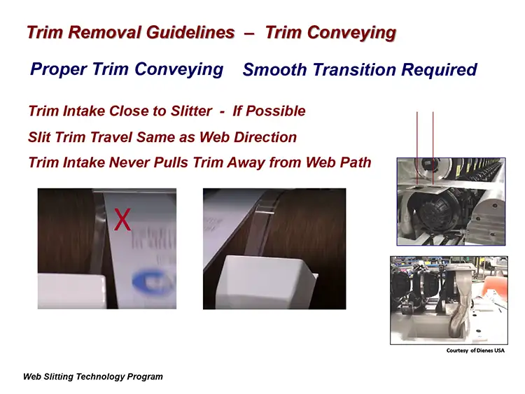
Trim-collection guidelines and process factors
Proper trim-strip conveying requires a smooth, low-stress transition after web fracture to the collection equipment intake. This should be as close as possible to the Cut Point. Trim travel should be in the same direction as the finished-roll web path and never pulled off of it. Any high axial-pull stress will create potential for a trim break, depending on the material (see Figure 7).
Years ago, during a client plant visit, I saw the trim bouncing erratically after the web fracture. There was zero trim-strip tension pull. Our old friend Gravity just hauled it to the floor after being fractured. Because I had seen this before, I immediately told the client this was a potential problem.
The material was a soft, low-temper foil that had a very narrow, very hard band adhered across the full web width about every 12 in. (305 mm) of web length. The slitting system was a Roll/Coil Shear design with non-contacting, driven rotary knives that created a tearing-type web fracture that easily broke the foil but not the tougher adhered band. It was very difficult to break. When the hard band finally fractured, the full trim strip “bounced” before heading to the floor.
Later, in a conference-room meeting to discuss my findings, thoughts and recommendations – and after a camera was mounted to the machine – we were able to watch the trim fracture action. Right before our eyes, the trim strip bounced up and fell onto the winding full-width web. The web broke, and the machine shut down. Better trim-collection control clearly was in order.
Handling and collecting trim at very high web speeds of 6,000 to 10,000 fpm (1,380 to 3,500 mpm) may require a special low-pressure air plate to slightly lift the trim to reduce web-contact drag. You may be shocked to read this, but static electricity can prevent you from having a clean Trim-Slitting fracture. And of course, a bin full of statically charged trim strip is dangerous.
Various web properties may call for various trim-removal designs. For instance, fibrous webs will find and snag on any protruding internal ductwork. Smooth internal tubing usually is needed to prevent duct clog. Abrasive or abrasive-coated webs will require metal ductwork because PVC ducts will wear away faster.
Slitting Logbook: A Holy Grail of Data
Back in 1980, before computers were everywhere in manufacturing companies, I joined a company with a 24/7 high-volume manufacturing process for hydraulic pump elements called gerotors. Our quality manager, Ed Romanski, had a mantra: “The system is the solution. Get the points and plot them.” His team took the production measurement data, he plotted the data manually and had the graphs taped all over his office walls. Ed had the manufacturing-process quality in control.
I was reminded of Ed’s mantra early in my slitting-industry career when I asked questions during a specific slitting-problem discussion with potential clients. One was, “Has this happened before?” Often the answer was, “I’m not sure” or “No.”
So, I strongly recommend that you have a historical Slitting Logbook to track your processes for future reference and positive process-improvements steps. This is if not for you, then for your replacement, when you get promoted to upper management.
For even more detail on this specific topic, take a look at my “Cut Points” column on page 20.
Dave Rumson has 12 years of experience as a slitting educator/consultant and more than 30 years of roll / shaft handling, unwind/rewind equipment and web-slitting experience. The past 20 years include 10 years with Dienes USA and Sigmala, Ltd., the latter having developed a computer/servomotor-controlled shear knifeholder. For 25+ years, Dave has developed and conducted technical presentations for CEMA, AIMCAL and TAPPI. He currently serves on the AIMCAL Technical Advisory Panel and its Web Handling Committee, and he writes the “Cut Points” Q&A column for Converting Quarterly. Dave also manages the 1,500-member Slitting Community Group on LinkedIn. He can be reached at 860-256-5658, email: drumson@maine.rr.com, www.drumson.wordpress.com.