
By Norbert Palenstijn, product sales development mgr., Leybold USA, Inc.
Editor’s Note: This paper is based on the author’s presentation at the ARC R2R USA Conference held in Milwaukee, WI, in October 2023.
Introduction
The predicate of R2R vacuum coating is evaporating a coating material and subsequently condensing this on a base material, referred to as the substrate. The substrate can be any material that can be rolled from one roll to another, including polymers, metal foils, textiles, nonwovens, and flexible glass or ceramics. There are different methods in which the evaporation is done, such as thermal evaporation, electron-beam (EB) evaporation and sputter (aka physical vapor deposition or PVD), but common among them all is that this is done in a vacuum environment. However, although creating the proper vacuum environment seems elementary, it is not a trivial task. To simplify this task and support customers, this firm developed a proprietary vacuum-simulation program, Pascal. There is a very basic version available to customers online, but to take full advantage of the benefits that it offers, an application review is done in conjunction with a dedicated applications engineer.
Why is vacuum used in coating? There are two main benefits for using vacuum:
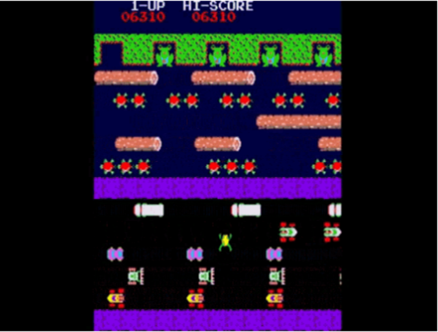
- To ensure a mean free path of evaporated atoms that is much longer than the distance from source to target. This ensures that the atoms have minimal interference and arrive unaffected by residual gas molecules and result in a smooth and even coating layer(s). A good analogy is the Frogger video-arcade game from 1981, with the “frog” (evaporated atom) trying to make it “home” (substrate) (see Figure 1). However, significant changes in mean free path lead to increasingly more complex vacuum-pump designs and calculations as pressure decreases.
- To provide cleaner surfaces. Otherwise, the evaporated atoms would not adhere well and would form an unstable layer(s).
Practical process steps to achieving a vacuum: The vacuum process can be broken down into two steps, both with differing process requirements:
- Create conditions for process initialization: This is the initial pump-down from ambient atmospheric pressure to the required vacuum level to start the coating process.
- Maintain conditions for process: Maintain operating pressures while flowing the required process gases and while maintaining conditions for a clear path for deposition materials to be coated.
Why use a vacuum-simulation program
The answer is easy; a vacuum system is the sum of all the components. When looking at a datasheet from a vacuum-pump manufacturer’s performance information, you see that it’s just at the pump inlet. However, from a process perspective, you’re interested at the vacuum levels at your point of use; in this case this is in the process chamber. In between the vacuum pump and the process chamber, there are piping and valves made of different lengths, geometries and materials, and these all have a net effect on the vacuum level achieved inside the process chamber. Modeling the impact that each of these individual components has is the key reason for using a simulation program. By changing the type and size of piping, you can see the net effect on pump performance.
The simulation program can be used both with designing a brand-new system or making improvements to an existing system. For example, this could be changing the size or material of the piping, or perhaps upgrading vacuum-pump technology from an older wet or oil-sealed pump technology to advanced vacuum dry-pump technology.
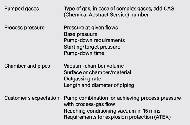
Customer application information needed: As far as the information needed to do a vacuum simulation, the name of the game is the more information the better. However, the minimal key information needed is shown in Table 1.
Simulation approach for process conditions and steps
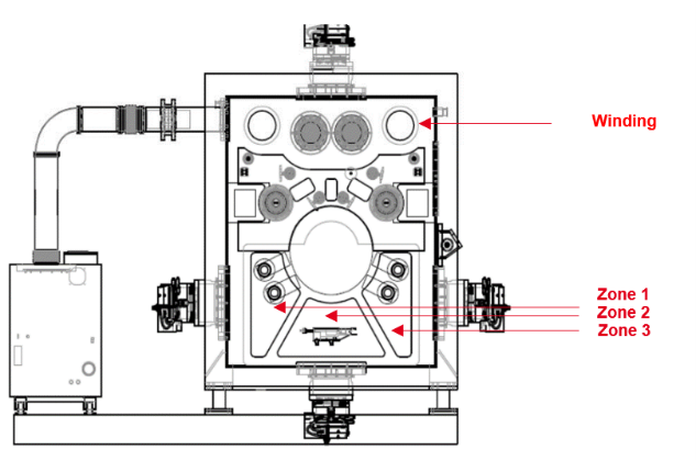
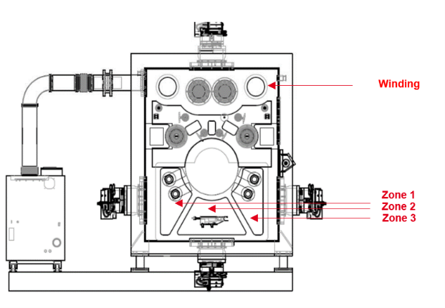
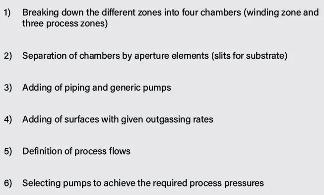
Based on the requirements provided by the customer, the application is modeled in the vacuum-simulation program in multiple steps. This is done for both the process conditions as well as for the pump-down. Figure 2 shows the modeling for a typical modular R2R-coating system that includes four areas to be evacuated. These are interconnected, but separated by slits that allow for the substrate to pass through: Winding, Zone 1, Zone 2 and Zone 3. The six-step simulation approach is described in Table 2. (For more detailed figures showing the simulation-process steps, go to www.convertingquarterly.com.)
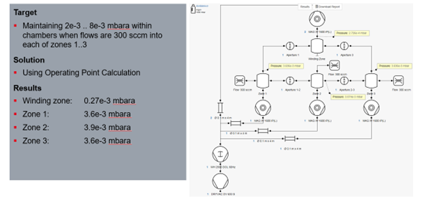
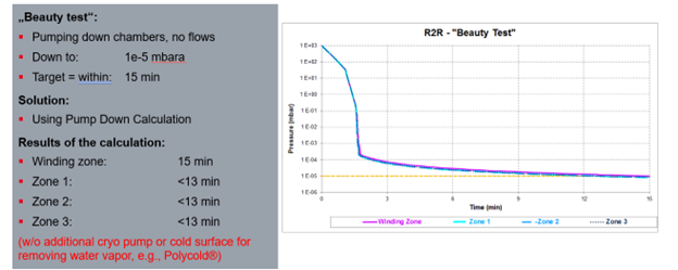
Simulation results
Based on the simulated R2R vacuum-coating system, the expected system performance of process conditions and pump-down is shown in Figures 3-4.
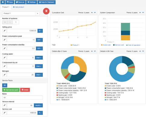
Calculation of cost of ownership for the pumping system: By providing the system investment cost, utility costs (such as electrical energy, purge gas, cooling water and service costs), the simulation program also can generate a “cost of ownership” overview per defined timeframe and split by tables and diagrams (see Figure 5).
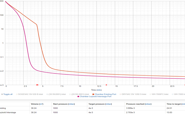
Savings: Earlier mentioned was one reason to run a simulation being upgrading vacuum-pump technology from an older wet or oil-sealed pump to advanced vacuum dry-pump technology. Figure 6 shows a real example of using this firm’s oil-sealed method and then replacing it with new dry technology. The change in pumps reduced the time required to reach the target pressure in the 3 E-4 range from 24.61 to 13.83 mins, resulting in a 12% increase in production.
Summary
Designing a complex vacuum system, as for R2R coaters, is not trivial. To achieve the expected vacuum-related results, it is important to know the exact process conditions. Piping, degassing, switching of valves, etc., have a big influence of vacuum performance. This is where experience and using a vacuum-simulation program add value to optimize the pumping system that ultimately leads to cost savings by reducing production times and increasing output. However, finding an optimum solution needs an experienced person knowing how to operate the simulation tool.

Norbert Palenstijn, product sales development mgr. at Leybold USA, Inc. (Export, PA), holds a Bachelor of Arts in International Business Management from the Inholland University of Applied Science. He has more than 25 years of industry experience with vacuum technology, custom engineered vacuum-pump systems, and industrial leak testing and detection systems. Norbert can be reached at 724-217-9667, email: norbert.palenstijn@leybold.com, www.leybold.com.